Migrating Arduino C to PICO C

Nothing to do with the subject of the post. Although the I guess you can see the “SEa”

You’d think it would be easy to move a C program from the Arduino platform to the Raspberry Pi PICO. After all, we have the wonderful libraries from Earle F. Philhower, III and the fabulous PlatformIO framework you can use to manage your project (don’t forget to perform this stuff before you try to build anything). And anyway, C is the same everywhere. Right?

Wrong.

When I write the Arduino stuff a while back I made one or two questionable design decisions. One of them was to use the char data type to hold 8 bit values. This was kind of OK back in the day (and by this I mean the 1980’s) but it turned out to be a stupid thing to do. Because some C compilers think that char holds a signed value (-128 to 127) and some think it holds unsigned (0 to 255). Of course the Arduino C compiler goes one way and the PICO C compiler goes the other way. Neither are wrong - the C language standard doesn’t specify this - and you could argue that anyone daft enough to perform maths with variables that are supposed to just hold character codes deserves all the trouble they get. But we are where we are, which in my case was looking at a program that has been working for years and has suddenly gone nuts.

I actually fixed it quite quickly once I figured out the stupid thing I’d done. The Pico debug probe proved very useful for this. I was able to set breakpoints in the timer interrupt handlers and then watch as various counters were updated. When I saw the code subtract 1 from 0 and get the answer 255 I knew exactly what had happened…..

Agile Octopus Tariff Display in HackSpace magazine

I get my copies of the magazine from Readly

If you’re wondering what that distant rumbling noise is, it might be crowds of people rushing to the newsagents to buy their copy of HackSpace magazine so that they can read my article in it.

Or it might be a bus going past.

Anyhoo, the article is out there. You can find the project on GitHub here.

They really knew how to make things back in the sixties

Started a new project today. I’m taking an old phone and making it more interesting. It’s going to have a Raspberry Pi inside along with extra circuitry to make the bell ring. Which is proving interesting. The bell in old phones is triggered by a 70 volt ac signal. Now, 70 volts is the far side of “tingly”. Anything below 50 volts is probably OK to grab hold of, but 70 could give you a shock you could do without. Especially at my age.

I’ve manged to get an inverter to convert 12 volts into a slightly less nerve jangling 35 volts or so. The plan is to drive the two coils that work the bell (you can just see them at the very top of the picture above) separately. So that I only use half the voltage. All I need is another MOSFET power driver (I’ve said this many times) so that I can control each coil individually. It should arrive tomorrow. I’ll add it to the circuit that I’ve already built which uses one MOSFET so that I can make the bell both “ding” and “dong”.

Agile Octopus Histograms

This is a very nice lcd panel

I spent some time today working on my Agile Octopus price display. Agile Octopus is an electricity tariff where you get a different price every half-hour during the day. A while back I made a device that would get the current price and display it, but now I’ve added a little histogram that displays upcoming prices for the rest of the day. The picture above was taken at 7:14 pm. The solid lines in the histogram are the hours and the dotted lines the half hour prices. On the right you can see the minimum and maximum prices. It looks like the prices will be going down over the evening. We’ve found this quite useful when deciding when to put the washing on or bake a cake. The display is powered by a Raspberry Pi PICO-W driving a rather nice LCD panel from Pimoroni.

It’s actually rather pleasing to make something that folks actually find useful and might even save us money.

Radios in tins = bad idea

Perhaps they might make a nice birthday present…

I’m making a new embedded device. It’s going to be a Bluetooth remote control. I’m on an upcycling kick at the moment, and in a tradition going back a while I thought I’d put the device in an Altoids tin. I bought the mints and then I realised that Bluetooth uses radio to work, and putting the PICO W in a metal box (i.e. Faraday cage) might not be for the best. Oh well.

Mdns makes your embedded devices easy to find

I’m making a network controlled light. The idea is that the light hosts a web site which you can find with your phone or computer. The light will have an internet (IP) address which you can use to locate it on the network (something like 192.168.50.5) but this might change as these addresses are assigned by your network router on a first-come first-served basis. What you really want to be able to do is refer to your light as “flashlight.local”. The mdns service makes this possible.

I’m using Circuit Python to host the website in a Rasbperry Pi PICO-W. They have a lovely HTTP server library which works a treat. It also supports mdns (Multicast Domain Name Server). This lets applications (for example your browser) ask if anyone on the local network has a particular name (in this case flashlight.local). The mdns server running on the PICO-W responds to these requests with a network address which can then be used to contact the PICO-W. The code below was added to the application and starts the service running. This code is slightly different from the example code for the service, but it does work very well.

import mdns


mdns_server = mdns.Server(wifi.radio)
mdns_server.hostname = "flashlight"

Once the server has been started it seems to just run in the background responding to requests.

This is the final website for the light

You can use this to make your embedded devices much easier to locate. If they get given a different IP address next time they start up they will just keep going.

Cockroach Circuits

I’d say “don’t do this at home” but I’m doing it at my home so it must be OK…

I can just about fit a PICO inside my remote controlled flash light, but there is hardly any room for anything else. So I’m using the “dead cockroach” hardware construction style. The circuit looks like a dead cockroach with wires standing in for legs. The connections are created by soldered wire-wrap wire into the holes in the board. I’m going to wrap the whole thing in insulating tape before fitting it into the flash. I like using wire-wrap wire. It is so flexible that it doesn’t tend to come undone from connections. I’ve got lots of different colours, which makes it much easier to follow. The circuit above is an implementation of this:

My level converter is blue though…

The important thing to do is keep testing as you build it, although so far it has kept working .

Hurray for Level Converters

At its brightest this pixel gives out 3 watts which is a lot of light

I’m working on my PICO controlled flashlight. Today it was time to wire up the output led. I’m using a Pixie light. This needs 5 volt levels to control it, but the PICO only produces 3.3 volts. This might just work (some things do) but I’m a bit concerned that if the power voltage for the lights gets a bit too high the light will not work or worse, be unreliable.

So I’m adding a level converter. These are very cheap and easy to buy (search for “arduino level shifter” on your favourite ecommerce site), but a bit of a pain to wire up as you have to connect input and output signals as well as power supplies and grounds for each side of the connection. However, as you can see above, the light works fine. Next I have to work out how to get the circuitry into the flash gun.

Remote Controlled Lights Working

This is the prototype light display

I’ve got the code for the remote controlled flash light just about working. It turns out to be a fairly simple matter to get a web site host running on a PICO and then get it to respond to incoming requests.

This is the interface to set the colour of the lights

I’m waiting for my super-bright led to arrive and then I’ll get the hardware built. Great fun. I’ll put all the code and designs onto GitHub when its finished.

Fun with a Flash Gun

Nothing like having an Auto Thyristor in your flash gun

We were out and about at Cottingham Day this weekend. I took loads of pictures using my Minox B on very old film. That didn’t end well. Which is why I have no pictures of the event at all.

While we were out I picked up this flash gun on a second hand stall. I fancied having another flash gun, particularly for two quid. Of course it doesn’t work. To be honest, I wasn’t expecting it to. These things don’t age particularly well and Cobra is not a name known for quality and longevity. In fact I until I found the flash gun I didn’t think it had anything to do with photography at all.

I’m not bothered though. I plan to take out the internals and replace them with a PICO-W to create a remote controlled light. I can use the battery compartment, reflector and even the flash zoom lens and my plan is to keep it looking as much like the original as possible.

The big grey thing is the capacitor. Need to be careful with that bit as it might have residual charge in it.

I’ve got the flashgun to pieces. Turned out to be quite easy. The main part is held together with little metal clips. The circuit boards are almost exactly the same size as PICO, which has got to mean something. Next step is to work out how to fit some lights inside.

Blue Chord Keyboard now in Hackspace Magazine

If you use both left handed and right handed keyboards at the same time you can channel your inner Rick Wakeman….

Issue 68 of HackSpace magazine is now out. On page 70 you can find my article that tells you how to create a Bluetooth connected chord keyboard using a PICO-W. There are lots of other great articles too. Well worth a read.

Bluetooth Chord Keyboard

Now avaialble for left and right handed users with adjustable key positions

The Raspberry Pi PICO-W powered Bluetooth Chord keyboard (I call it “Blue Chords”) is now on GitHub. You can find it here. I’ve updated the code to use the latest version of the Raspberry PI PICO SDK and updated the PC design and matching case design.

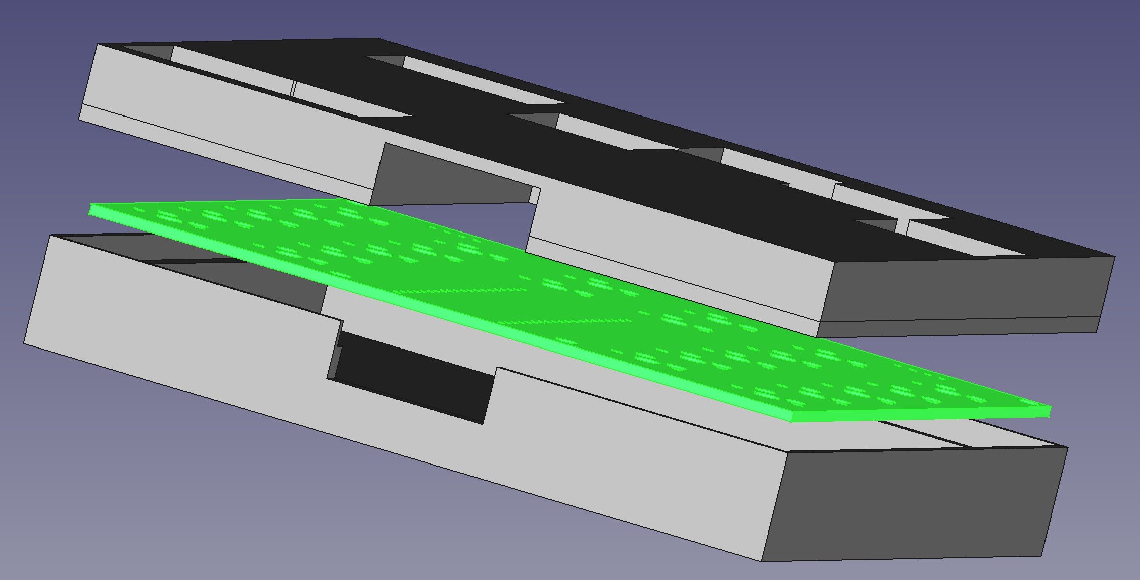
I used the Kicadstepup plugin to import the board into the design

I’ve built some prototypes (you can see them at the top) but I’ve not built the final design yet. The project will be the basis of an article in an upcoming HackSpace magazine.

Lovely OLED driver for the PICO

It can say other words as well…..

I spent a chunk of the day trying to get the OLED display working on the keyboard I’m building. It works fine under Python, but it was a bit reluctant to work under C++. In the end I found this lovely OLED library: https://github.com/daschr/pico-ssd1306 It's very lightweight and easy to configure and use. It worked a treat. The display that I’m using is the monochrome version and it looks really, really good.

Achievement unlocked: First PCB built

The bag was very hard to undo, but worth it

A parcel arrived from PCBWay today. These are the boards that I designed last week. They turned them round in double quick time and they look great.

These are the key positions for right handed use

I lost no time soldering the key sockets into place and getting a test program into the PICO. I have made a few mistakes with this board. The key spacing is a tiny bit close. I had to file a bit off a couple of keytops to make them move smoothly. The next version will have the keys a mm or so further apart.

It is traditional that your first board needs a fix or two….

I’d also made a mistake with one of the OLD display sockets, reversing the clock and data lines. But I managed to fix that and get the board going with some Python code. The good news is that the left handed versions is wired perfectly. I’m going to build one of those too just to see if it is easy to learn to use the keyboard with your left hand. Now I have to write the C++ code to read the keys and send the keypresses over Bluetooth.

Achievement unlocked: designed KiCad circuit board

I’m rather proud of this. Please don’t find a fault in it…

I’ve finished my design for the chord keyboard. There are lots of key locations but you only put one switch in each column. This makes it easy to make left or right handed versions. I’ve added connections for a tiny OLED screen. You fit the display the the side that you are not using.

Next thing to do is to send it off to get some boards made. Rather exciting.

PICO Examples vs OneDrive - Fight!

Size comparison with an SD card. Remember them?

I’m doing some work on the Raspberry Pi PICO. To make things easier I bought a debug probe. It’s tiny. It comes with all the cables that you need for your PICO, but you do need to solder three pins onto your PICO device to connect it up. That is, unless you get the much sought-after “H” versions of the PICO which come with pre-soldered pins and a tiny socket that connects directly using the cable provided with the kit.

It works a treat. Rob’s pro-tip: read the instructions very carefully and do all the steps, otherwise getting it working takes twice as long.

I installed the PICO SDK using a script you can find here. The script works fine, but by default it installs the examples into one of your document folders (or at least it did for me). I use OneDrive for file synchronisation and the next thing that happend (at least on my machine) is that OneDrive went nuts and started uploading thousands of tiny files into the cloud. I don’t remember seeing an option to install the examples somewhere else when I ran the script, but if you do the install I’d strongly recommend you look for it and put the examples somewhere in a folder which is not being synced with the cloud.