Great Hardware Meetup : Everything working by 6:30 pm

Eveyrthing Working

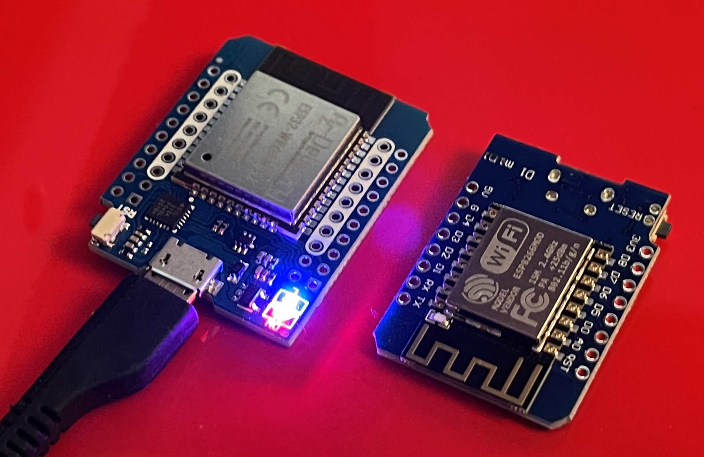
We had a great Hardware Meetup last night. Not a huge number of people, but an awful lot of expertise. I took along a new ESP32 device I’d just received from China. I was planning to use it in place of the Wemos D1 Mini device that I’ve been using for ages. I was making the switch because I couldn’t find any drivers to connect a D1 Mini to my shiny new Snapdragon powered laptop. Imagine my amusement to discover that the new device I’d bought used the same CH340 usb interfaces as the D1 Mini and wouldn’t work either. Wah.

But then Ben didn’t believe me when I said that there are no CH340 USB-to-serial drivers available for my Snapdragon powered Windows 11 notebook. He did some digging and found me the manufacturer’s proper download site: https://wch-ic.com/downloads/CH341SER_EXE.html I installed the ones from this site and they worked a treat. This is a big win for me. It makes the new notebook even more perfect.

So then it was on to the project for the evening. I’ve been meaning to add a Connected Little Box which can display text messages. I bought a little LCD panel for the princely sum of 2.64 It comes with an adapter that lets you use it from I2C, which makes the wiring much simpler. I’ll do a detailed post about it later. We found the drivers, added them to my PlatformIO project and had the LCD panel working in about ten minutes. Pro tip: if you can’t see anything on the screen you should adjust the contrast.

So, half an hour before the end of the meetup I had got everything working that I’d brought with me. The next meetup is in two weeks on the 27th of November. I’ll have to bring along something more difficult next time.

In the meantime Brian and David were playing with a rotating Lidar sensor and Richard was showing off new kit and working on an old-school embedded device.

And we rounded if off with a nice meal at the Omlette. Good times.

Debug ESP32/ESP8266 programs in PlatformIO using the exception decoder

This is the prototype. I think I need to make a PCB for this..

I’ve been hard at work adding RFID abilities to Connected Little Boxes. It’s going mostly OK. It worked first time, which I hate because it means that the pain comes later. And it did, in the form of random crashes. The program would run for a while and then reset with an exception. The ESP devices produce a lump of debug output when they fail, but you then have to decode this text. The great news is that this behaviour is built into PlatformIO, the wonderful tool that I’m using to make the application. All you have to do is add the following line to the platformio.ini file in your project:

monitor_filters = esp8266_exception_decoder

The serial monitor will now look for the messages that mark the start of the debug information and then use the build file to tell you where the program was when it fell over. Very useful. In my case it allowed me to determine that the program was failing in WiFi code, not something that I wrote. Of course, even though it is not failing in my code, I still have to fix it. I have two golden rules when debugging embedded code:

  1. First check the power supply.

  2. Second check the memory allocation.

In this case the power is OK, so the problem must be memory. I thought I had enough free memory for the system keep going but this turned out not to be the case. I freed up a bunch of space and the device has been running solidly ever since.

Using the second serial port connection on the ESP8266

Perhaps not many of you have had problems with the serial port connections on your ESP8266 devices. But I’m going to write this down anyway. Here’s the problem:

The ESP8266 has one and a half serial ports. But I want my ESP8266 to use serial connections to two different devices:

  • I want to be able to connect my computer to the ESP8266 so that I can load programs into the device and set configuration options.

  • I want the ESP8266 to be able to talk to a Pixelbot robot and tell it what to do.

Connecting the ESP8266 serial signals to the robot processor breaks the serial connection to the computer. So if I want to connect my robot to the my PC I have to unplug connections on the robot itself. Which is tiresome. So instead I’m using a little know feature of the ESP8266. It can swap the serial connections to different processor pins. So I can connect the robot serial signals to GPIO 13 (TX) and GPIO 15 (RX) and, once my program has started running I can call a function to swap the serial signals over to these pins.

Serial.swap();

After swap has been called code in the robot using the serial port will send messages out of the alternate pins. When the robot starts up it looks for messages on the original connection and if it doesn’t see anything it swaps the connection. This makes it much easier to use. This is the kind of kludge I’m proud of.

ESP resources from Rob

Sprockets are apparently in…

I got a nice comment from Dave which also asks about any resources for the ESP8266 or the ESP32 devices. I thought I’d pop the answer in a blog post.

You can find all my ESP32 blog posts here. You can find all my ESP8266 posts here. I’ve written a bunch of articles for HackSpace magazine which include ones about ESP devices which you can find here. I’ve got a bunch of project repositories which include those devices on my GitHub pages here. I hope you find them all useful. Or at least one or two.

Chunking your ESP32 Web responses

Note that this is not actually how computer memory works

Great title for a blog post eh? One of the wonderful things about modern embedded devices is that they can host web sites. You can use your phone to browse content served by a device that cost less than a pint of beer. Although some people prefer to buy the beer.

Anyhoo, I’ve been making devices that host web pages as part of the configuration process for my Connected Little Boxes. You turn the device on, scan a QR code with your phone which connects to a WiFi hotspot served by the device and then scan another QR code to get to a configuration page so that you can enter your local WiFi credentials and generally set the device up. This is how lots of connected devices work, and I wanted to make my own system for doing this. And I ran into problems with memory. Not forgetting what I’m supposed to be doing (ho ho) that happens all the time. More like the way that once I’ve got everything running on my little ESP device I’ve got hardly any memory left for large things (comparatively) like web pages.

Now, one way to serve out a web page is to put the page content into a string and then send that string out. This works, but you need enough memory to hold the entire string. Which it turned out I didn’t have. So a better way is to send the page a chunk at a time. The ESP8266 web server has a way of doing this:

server->chunkedResponseModeStart(200, F("text/html"));
server->sendContent(settingBuffer);
server->chunkedResponseFinalize();

The first statement tells the server I’m sending a bunch of chunks. The second statement sends a chunk of text from the settingBuffer string. You can send as many chunks as you like. The third statement ends the chunking. Very useful, particularly when you discover that you can send out chunks of text that are stored in program memory rather than ram.

So I got all this working and then I wanted to move the code to the ESP32 device. This chip is a bit more expensive than the ESP8266 but it is a lot more powerful. And it doesn’t do chunking. Wah!. Fortunately I found this wonderful post which told me how to extend the ESP32 web server to make chunked responses work in the same way as the ESP8266. It will be part of the latest version of the Connected Little Boxes embedded code (tentatively titled HULLOS-X) soon.

Making lots of WiFi

I’m trying to track down the cause of my network problems at the Bonus Arena on Monday. One possibility is that a large number of available WiFi connections might cause the joining software to run out of memory.

So today I tried to make a large number of access points using a box full of ESP8266 devices. I got up to 14 access points and my software still worked fine. I think I’m going to have to go into town with a system and have a proper play to find out what is going on.

Restoring Arduino servo movement

clb turner.png

Servos are a great, cheap, way of giving your devices a bit of physical movement. You can pick little ones up for around a pound each and a single Arduino can control quite a few servos. You can make a Connected Little Box control a servo. In the example shown above you turn the knob on the left and the servo on the box on the right turns, tracking it. However, there are two bad things that a servo can do:

  1. Not move as far as you might want it to.

  2. Burst into flames trying to move to a point that it can’t get to.

The writers of the Arduino servo library have decided that point 2 is actually more important than point 1. So they’ve changed the way that the servo libraries work. This caused some of our servos to misbehave. How did we fix them? Read on…..

When you want a servo to move you give it a pulse of a particular length. The servo converts this pulse into a value which is matched against one that represents the position of the servo output shaft. The servo attempts to turn the shaft so that the two values are the same, causing it to move to a particular position. If something tries to move the shaft away from this position the servo will push back. If the pulse size changes the servo will move the output shaft in response. So far, so wonderful.

But what happens if the computer gives a pulse that is converted to a value that the servo shaft can’t match? The answer is that the servo will try to move to that position and get stuck on the way, stubbornly pushing until coils heat up and melt, gears break and so on. And then you have to buy a new servo.

The original Arduino libraries for the servo assumed a range of movement that some servos can’t match. So they’ve reduced this range. The range boils down to two values that used to be 544-2400 but are now 1000-2000. The new range makes servos a lot safer, there is less chance that they will move into dangerous positions, but it does significantly reduce the amount of movement that you get. The good news is that you can override the pre-set values when you attach to your servo:

servo = new Servo();
servo.attach(2,544, 2400);

The statements above show you how to do this. The first statement creates the servo. The second attaches the server to GPIO pin 2 and restores the range of movement to the values used in the bad old dangerous days.

Debugging with Magic

Trying a new blogging approach. Blogging when I have something to say, rather than fretting about making a post every day……

Only a code magician can fix a program by renaming a variable. That’s me.

I’ve just encountered an hilarious (and by hilarious I mean horrible) bug with an upgrade to the ESP8266 compiler. I’ve been building my Connected Little Boxes software for quite a while now and it just works. Today I noticed that I had upgrades to the Espressif SDK in Platform IO. So, like a fool (and I do mean that) I pressed OK to upgrade them.

And suddenly my newly built program broke. It would start running and then spontaneously explode with Exception(29). Which means that my program is twiddling a memory location that is not where it should be.

First step was to recompile the code for the ESP32 processor (my code works on both). That worked fine. OK, so it is not necessarily something stupid that I’ve done. Back to the ESP8266.

It’s hard to debug code running in a separate device, but after a few minutes (I am pretty good at this - although I was slowed down as bit by the way that the bug vanished when I enabled debug mode) I’d isolated it to this statement:

RegistrationProcessDescriptor.status = REGISTRATION_OFF;

It runs during startup and turns off the registration process. But I guess you’d already worked that out because my commenting game is so good. Anyhoo, when this statement runs the device explodes.

OK. Welcome to planet weird. First thought is that RegistrationProcessDescriptor is not pointing to the right place. But it is. Otherwise the call to the exploding function would not have worked. So, second thought is that REGISTRATION_OFF is a silly value. It isn’t. It’s 1004 since you asked. And status is an integer property in case you were wondering, so everything make sense and the code has been working perfectly for ages…..

Of course I’ve fixed it. I’ve renamed the variable RegistrationProcessDescriptor to RegistrationProcess. Something deep in the compiler must be getting upset about long variable names and dropping dodgy code. There were a few clues:

  • It works with a different compiler

  • It worked when I changed the code a bit (by adding debug)

  • The variable name was a bit longer than ones I normally use

I’m not happy that the problem occurred, but I’m pleased I was able to fix it.

Simple encryption with the ESP32

esp32andesp8266.jpg

Early versions of the software for my Connected Little Boxes stored all the settings in an area of EEPROM memory. This is because the settings code was originally written to run on an Arduino Uno which only provides EEPROM as persistent storage.

Now that I’m using a the ESP8266 and ESP32 I can use a proper file system to store the settings for a device. This is nice, but has left me with a problem. On the Arduino Uno I was quite happy to store passwords in EEPROM. My software won’t let you read back the contents of password settings, you can only put values in. If you want to read the settings you’d have to get hold of the device and then swap the internal program for one which shows you the contents of the EEPROM. But with the new code I’ll have a bunch of files on the device which someone might be able to just take a look at.

So I started looking at really simple encryption. Not really encryption as such, just something to make it impossible for someone reading one of the settings files to be able to read back the values of protected settings. It’s not really proper encryption as the key and the code which uses it are both stored in the device so anyone with the time and the inclination could break it. However, I think what I’ve done is OK for its purpose.

#if defined(ARDUINO_ARCH_ESP32)
#define PROC_ID (unsigned long)ESP.getEfuseMac()
#endif

#if defined(ARDUINO_ARCH_ESP8266)
#define PROC_ID (unsigned long)ESP.getChipId()
#endif

#define ENCRYPTION_SALT 1234

void encryptString(char * destination, int destLength, char * source)
{
    randomSeed(PROC_ID+ENCRYPTION_SALT);
    int pos = 0;
    char * dest = destination;
    destLength= destLength -1;
    while(*source)
    {
        int mask = random(1,30);
        *dest = *source ^ mask;
        dest++;
        source++;
        pos++;
        if(pos==destLength)
        {
            break;
        }
    }
    *dest=0;
}

This is my encryption code. You give it a string and it scrambles the text. I’ve done it this way so that the characters codes still remain in the printable ASCII range. I use the processor ID number of the device and a salt value for each device to seed the built-in random number generator. I then use the magic of exclusive-or to scramble the text. The decrypt process is exactly the same code.

It seems to work OK. I only encrypt the passwords themselves. This reduces the amount of data that a cracker has to work with. You could crack it using any one of a number of attacks, but what you can’t do is just read out the text from a settings file and then use it, which is the level of security I wanted.

The way I see it, once someone gets hold of your physical device all bets are off security wise. Particularly if the algorithm is in the public domain too. That’s why I advise you to make a guest WiFi network for your IoT devices so that you can reduce the effects of a security breach.

Using the ESP8266 Real Time Clock memory to manage device reboots

newclb.png

The ESP8266 device has a built in Real Time Clock (RTC) that can work as, well, a real time clock. This is very useful if you want to put the processor to sleep for a while in low power mode and have it wake up later. The RTC also contains a small amount of memory which is maintained in low power mode. You would put values into this that you wanted to remember when the device wakes up again.

You can also use RTC memory to store values that will be retained when the device is rebooted. After a reboot you can’t make any assumptions about values that might or might not be in memory, but you can assume that the RTC memory values are intact.

I’m using this ability to allow an ESP8266 to reboot in different “modes”. The problem that I am solving is that there is not enough memory in an ESP8266 to allow it to run the Connected Little Boxes software and a web server at the same time. My program sets the type of device it needs into RTC memory and then resets the device. When it starts running it reads the value back and then starts in the requested mode.

int getInternalBootCode()
{
    uint32_t result;
    ESP.rtcUserMemoryRead(0, &result, 1);
    return (int)result;
}

void setInternalBootCode(int value)
{
    uint32_t storeValue = value;
    ESP.rtcUserMemoryWrite(0, &storeValue, 1);
}

The getInternalBootCode function returns the contents of the value at the start of the RTC user memory. the setInternalBootCode function sets it. The functions use the ESP.rtcUserMemoryRead and ESP.rtcUserMemoryWrite functions which transfer a block of data between the program and the RTC memory. The first parameter is the offset into the RTC memory (I’m using 0 to indicate the start of the memory). The second parameter is a pointer to a 32 bit data value. The third parameter is the number of 32 bit values to transfer. I only want the one value for my boot code. Now I can store it and fetch it back.

Using the Second Serial Port on the ESP8266

Wemos Printer .png

The ESP8266 processor chip has one and a half serial ports. One has both TX and RX connections, so that it can both send out data and listen for incoming data. This is port usually connected to via USB to the host computer and used to send programs into the device and to have conversations with our running programs. We can use this port to connect to other things but this makes it hard to interact with our device.

The other “half serial port” on the ESP8266 is a port that can only transmit data. That’s fine for me at the moment as I only want to send data to a printer. The TX signal for this port is connected to D2 on the ESP8266 and which is wired to pin D4 On the WEMOS D1 Mini, as shown in the diagram above. For numbering reasons (computer people like to start counting at zero) the second printer port is numbered Serial1. You can open and use it in the same way as the other port:

Serial1.begin(19200); // open the port at 19200 baud
Serial1.println(“hello”);

Your program can try to read from this port, but it won’t see any data.

What about SoftwareSerial?

At this point you might be asking “Why doesn’t Rob just create a software serial port and have done with it?”. Good question. A software serial port is a piece of code that twiddles a data output as if it was being driven by serial port hardware. This is called “bit bashing” because the code “bashes” the data out.

The only problem with a software serial port is that it usually requires the sole attention of the processor when it s being used. I thought when I first saw these that they might do cunning things with timers and interrupts that meant that they had no impact on performance, but this is not the case. If you use SoftwareSerial you will find that your program is effectively stopped while it sends and reads data. That might be OK for you, but not for Rob. I don’t want the lights on my Connected Little Box device to flicker when it prints something. So I much prefer a physical port which sends each byte of data without the involvement of the processor.

Rob’s Amazing Interrupt Driven Serial Port

On a slightly different topic, if you need to connect a very large number of serial ports to an ESP8266 device and you don’t want to use Software Serial to read them all (which usually doesn’t work if you have more than a couple of inputs) you might like to take a look at my “edge triggered serial port” code here. This is a Software Serial implementation that only stops the processor when it sees the edges of serial data.

Using the ADC on a Wemos ESP8266 device

I want to use an analogue to digital converter in my Connected Little Boxes project to convert a rotary position as set by the knob on the left hand box in the picture into a number I can use to control the servo on the right hand box. I like the idea of moving physical movement from one place to another.

An analogue to digital converter (ADC) is a piece of hardware that takes in a voltage and gives you a number that represents the level of the voltage. ADCs are useful to measure things like the battery voltage levels and for converting analogue sound signals into a sequence of digital values.

A potentiometer is a special kind of resistor. Turning the shaft of the potentiometer moves a contact along a circular carbon film in a way that allows the output to produce a different voltage output depending on the position of the contact. If I connect the output of the potentiometer into the ADC of my ESP8266 I can write a program that will read the position of the potentiometer and use this to control the servo.

wemosADC.png

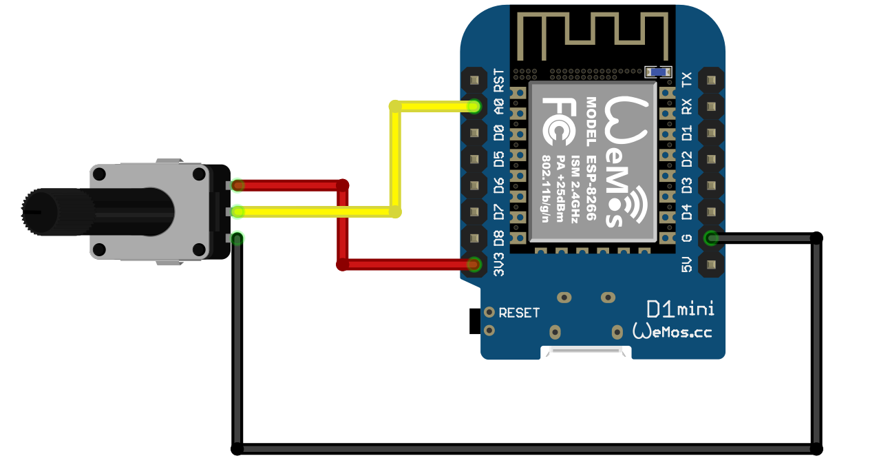
The ESP8266 chip has a single ADC device which reads signal levels up to 1.8 volts or so. The good news is that my favourite ESP8266 based device, the Wemos D1 mini, has a “potential divider” circuit on the board that allows the input to accept inputs up to the 3.3 volt power supply. You can wire it up as shown above. Remember to use the 3v3 pin rather than the 5v one. Turning the knob on the potentiometer will move the input on the A0 pin between 0 and 3.3 volts.

You can use the ADC in your program like this:

int reading = analogRead(0);

If the input sees 0 volts you get the value 0 set in the variable reading. If the input sees 3.3 volts you get the value 1023. The numbers are fairly steady, although I see a bit of noise which causes the values to “jitter” around a bit. I’ve added some code that ignores changes of around 5 or so in the value.

I send the reading value across to the little box on the right of the picture above so that the position of the servo tracks the knob. It works really well, but in making it work I learned something which you might find useful to impress people with at any parties (or Microsoft Teams meetings) that you might go to in the future.

ADC Problems with the ESP8266

It turns out that reading from the ADC on an ESP8266 gets in the way of setting up a WiFi connection. If the device is connecting to a WiFi access point and your program reads the ADC while this is happening the connection will not be setup properly. I’ve had to modify the code so that it only starts to read from the ADC once a connection has been established.

ESP Reset Message Strings

Have you ever wanted to print out the reason why your ESP32 or ESP8266 has just reset?

No?

Must be just me then. Anyhoo. If you do want to do this, here’s the code to do it. You’re welcome.

void getBootReasonMessage(char *buffer, int bufferlength)
{
#if defined(ARDUINO_ARCH_ESP32)

    esp_reset_reason_t reset_reason = esp_reset_reason();

    switch (reset_reason)
    {
    case ESP_RST_UNKNOWN:
        snprintf(buffer, bufferlength, "Reset reason can not be determined");
        break;
    case ESP_RST_POWERON:
        snprintf(buffer, bufferlength, "Reset due to power-on event");
        break;
    case ESP_RST_EXT:
        snprintf(buffer, bufferlength, "Reset by external pin (not applicable for ESP32)");
        break;
    case ESP_RST_SW:
        snprintf(buffer, bufferlength, "Software reset via esp_restart");
        break;
    case ESP_RST_PANIC:
        snprintf(buffer, bufferlength, "Software reset due to exception/panic");
        break;
    case ESP_RST_INT_WDT:
        snprintf(buffer, bufferlength, "Reset (software or hardware) due to interrupt watchdog");
        break;
    case ESP_RST_TASK_WDT:
        snprintf(buffer, bufferlength, "Reset due to task watchdog");
        break;
    case ESP_RST_WDT:
        snprintf(buffer, bufferlength, "Reset due to other watchdogs");
        break;
    case ESP_RST_DEEPSLEEP:
        snprintf(buffer, bufferlength, "Reset after exiting deep sleep mode");
        break;
    case ESP_RST_BROWNOUT:
        snprintf(buffer, bufferlength, "Brownout reset (software or hardware)");
        break;
    case ESP_RST_SDIO:
        snprintf(buffer, bufferlength, "Reset over SDIO");
        break;
    }

    if (reset_reason == ESP_RST_DEEPSLEEP)
    {
        esp_sleep_wakeup_cause_t wakeup_reason = esp_sleep_get_wakeup_cause();

        switch (wakeup_reason)
        {
        case ESP_SLEEP_WAKEUP_UNDEFINED:
            snprintf(buffer, bufferlength, "In case of deep sleep: reset was not caused by exit from deep sleep");
            break;
        case ESP_SLEEP_WAKEUP_ALL:
            snprintf(buffer, bufferlength, "Not a wakeup cause: used to disable all wakeup sources with esp_sleep_disable_wakeup_source");
            break;
        case ESP_SLEEP_WAKEUP_EXT0:
            snprintf(buffer, bufferlength, "Wakeup caused by external signal using RTC_IO");
            break;
        case ESP_SLEEP_WAKEUP_EXT1:
            snprintf(buffer, bufferlength, "Wakeup caused by external signal using RTC_CNTL");
            break;
        case ESP_SLEEP_WAKEUP_TIMER:
            snprintf(buffer, bufferlength, "Wakeup caused by timer");
            break;
        case ESP_SLEEP_WAKEUP_TOUCHPAD:
            snprintf(buffer, bufferlength, "Wakeup caused by touchpad");
            break;
        case ESP_SLEEP_WAKEUP_ULP:
            snprintf(buffer, bufferlength, "Wakeup caused by ULP program");
            break;
        case ESP_SLEEP_WAKEUP_GPIO:
            snprintf(buffer, bufferlength, "Wakeup caused by GPIO (light sleep only)");
            break;
        case ESP_SLEEP_WAKEUP_UART:
            snprintf(buffer, bufferlength, "Wakeup caused by UART (light sleep only)");
            break;
        }
    }
    else
    {
        snprintf(buffer, bufferlength, "Unknown reset reason %d", reset_reason);
        break;
    }
#endif

#if defined(ARDUINO_ARCH_ESP8266)

    rst_info *resetInfo;

    resetInfo = ESP.getResetInfoPtr();

    switch (resetInfo->reason)
    {

    case REASON_DEFAULT_RST:
        snprintf(buffer, bufferlength, "Normal startup by power on");
        break;

    case REASON_WDT_RST:
        snprintf(buffer, bufferlength, "Hardware watch dog reset");
        break;

    case REASON_EXCEPTION_RST:
        snprintf(buffer, bufferlength, "Exception reset, GPIO status won't change");
        break;

    case REASON_SOFT_WDT_RST:
        snprintf(buffer, bufferlength, "Software watch dog reset, GPIO status won't change");
        break;

    case REASON_SOFT_RESTART:
        snprintf(buffer, bufferlength, "Software restart ,system_restart , GPIO status won't change");
        break;

    case REASON_DEEP_SLEEP_AWAKE:
        snprintf(buffer, bufferlength, "Wake up from deep-sleep");
        break;

    case REASON_EXT_SYS_RST:
        snprintf(buffer, bufferlength, "External system reset");
        break;

    default:
        snprintf(buffer, bufferlength, "Unknown reset cause %d", resetInfo->reason);
        break;
    };

#endif
}

You pass the function a pointer to a buffer and the size of that buffer. The function then works out what kind of device you are using and then creates a message for that device. This is how you use it:

#define BOOT_REASON_MESSAGE_SIZE 150
char bootReasonMessage [BOOT_REASON_MESSAGE_SIZE];
getBootReasonMessage(bootReasonMessage, BOOT_REASON_MESSAGE_SIZE);
Serial.println(bootReasonMessage);

Using ESP32 and ESP8266 with the same source file

If you want to use the same solution on both ESP8266 and ESP32 devices you find that there are a few inconsitencies between their libraries and include files. I've made this tiny set of conditional includes which pulls in the properly named elements for each processor. It also provides a symbol called PROC_ID that returns the processsor ID in a way that can be used in both types of program.

#if defined(ARDUINO_ARCH_ESP32)

#include <Arduino.h>
#include <WiFi.h>
#include <DNSServer.h>
#include <WiFiUdp.h>
#include <WiFiServer.h>
#include <WiFiClient.h>
#include <WiFiClientSecure.h>
#include <HTTPUpdate.h>
#include <WebServer.h>

#define LED_BUILTIN 2

#define PROC_ID (unsigned long)ESP.getEfuseMac()
#define PROC_NAME "ESP32"

#endif

#if defined(ARDUINO_ARCH_ESP8266)

#include <Arduino.h>

#include <ESP8266WiFi.h>
#include <PubSubClient.h>
#include <WiFiClientSecure.h>
#include <ESP8266httpUpdate.h>
#include <ESP8266WebServer.h>

#define PROC_ID (unsigned long)ESP.getChipId()
#define PROC_NAME "ESP8266"

#endif

Just put this at the top of your program and when you build your program it will pull in the files that it needs.

Using an M1 Powered MacBook to program ESP8266 devices

I’m loving my new M1 powered MacBook Air. The hardware makes a perfect laptop. It just works, goes very fast and is always there. The battery life is more like an iPad than a laptop. It doesn’t run Windows 10, so it isn’t perfect, but I’m slowly getting my head around Mac OS (WHY IS FOLDER NAVIGATION SO HARD???) .

I’m still using the Microsoft tools I use most of the time - Visual Studio Code, Word and PowerPoint all work perfectly. I’m using the Safari browser at the moment, but I’ll switch to Edge when they release a version that uses the M1 processor.

Anyhoo, I’ve been building code on the MacBook for my ESP32 and ESP8266 devices. As I reported a while back, there is a fault with the serial port auto-discover in the version of Python used by Platform IO (my embedded development environment of choice). I got round this by deleting some lines from the Pytool program that caused the error, you can find out more here. Then I hard-wired the name of the target device into my PlatformIO project.:

Mac OS uses Unix style names for its serial ports. If you want to find out the name of the port that your Wemos is plugged into you can use this command at the command prompt:

ls /dev/tty. usb*

This displays a directory listing of all the usb devices that are presently connected. My Wemos was called /dev/tty.usbserial-140. Yours will almost certainly be different.

upload_port = /dev/tty.usbserial-140

Once you know the port you can then add a line to the Platform.ini file to explicitly target this port when you deploy.

I’ve also discovered another issue; deploying a program to an ESP8266 seems to fail with a timeout problem. The best way to fix this seems to be by reducing the upload speed by adding this line to your ini file.

upload_speed = 115200

It takes a bit longer to deploy, but it does get there.

Enter the Wemos D1 mini ESP32

Wemos D32.png

I really, and I mean really, like the Wemos D1 mini. Part of this is because I can get them for under two pounds each, but I do reckon that they make the best connected embedded platform you can get.

Unless you need Bluetooth, or want to talk using secure sockets. Or you fancy writing a MicroPython program longer than a few lines. Then you need an ESP32. Up until recently my weapon of choice for ESP32 applications was the DOIT platform. It’s cheap, it works and it has lots of pins. However, it does have one really annoying limitation. You have to press the program button, or the reset button, or some horrid combination of them each time you want to deploy a program to it.

The Wemos D1 Mini ESP32 doesn’t have this limitation. You can deploy programs and it just works. It has lots of pins but you don’t have to use all of them. It is very similar in size to the original D1 Mini (above on the right), and the pins have been arranged so that you can connect original shields and make them work. It’s a bit more expensive than the original, but well worth the money I reckon.

Using WS2811 Light Strands with the WEMOS D1 Mini

wired lights.png

A very long time ago I spent some time doing stage lighting. Great fun and only occasionally extremely dangerous. Like the time when a friend of mine extended a wire with a plug in extension and he got the plug and the socket the wrong way round. He had the mains coming out of the plug and going into the socket. It was perfectly safe. Until the plug came out…

What has this to do with WS8211 light strands I hear you asking? Well, the strands are fitted with a plug at one end and a socket on the other. Because I know about these things, I decided that the plug would be the connector on the light strand that would receive the power and data signals. My decision was nicely reinforced by the way that the leds had a nice big arrow pointing inwards on this connection. Armed with this knowledge I wired everything up to find that it didn’t work.

Actually, I was kind of expecting this to be the case. Some leds like this need more voltage swing than can be provided by the 3.3 volts that the Wemos puts out. So I used a level converter to bring this up to nearly 5 volts. And of course it still didn’t work. After a bit of testing and a lot of head scratching I did what I should have done right at the start. I tried the led strand with something that was bound to work; in this case an Arduino Uno that puts out 5 volt logic. Of course they didn’t work with that either. So, in a spirit of “what’s the worst that could happen?”, I tried sending signals and power into the socket on the other end of the wire.

Of course it worked. So, if you want to use a Wemos D1 Mini with these led strands just make sure that you ignore the arrows and wiring common sense and send your signals into socket end of the strand. The really good news is that you can probably connect the Wemos directly to the led strand. My leds work without my carefully assembled level converter.

The only other thing to remember is that the RGB order is different for these strands. Blue and white will look fine, but everything else will look wrong because the red and the green colours are swapped. I’ve added a configuration option to allow the user of a Connected Little Box to set the type of leds:

switch(pixelSettings.pixelConfig)
{
    case 1:
    strip = new Adafruit_NeoPixel(pixelSettings.noOfPixels, pixelSettings.pixelControlPinNo, 
    NEO_GRB + NEO_KHZ800);    
    break;
    case 2:
    strip = new Adafruit_NeoPixel(pixelSettings.noOfPixels, pixelSettings.pixelControlPinNo, 
    NEO_KHZ400+NEO_RGB);
    break;
    default:
    strip=NULL;
}

Config 1 is “normal” NeoPixels and config 2 is the settings that work best for the strands.

ESP8266 int alignment fun

OK. Pop quiz. What’s wrong with the following C++ code?

unsigned char * chPtr;
int * intPtr;

// point chPtr at a buffer somewhere

// get an integer out of the buffer
intPtr = (int *) chPtr;
Serial.println(*intPtr);

Perhaps a bit of context would help. I use commands like this to tell my Connected Little Boxes what to do:

{"process":"pixels","command":"setrandomcolour",
"pixelSpeed":10, "sensor":"button","trigger":"pressed"}

This command means “send the command setrandomcolour” to the pixels process when the user presses a button. Fade the colour over 10 “ticks”. This means that each time the user presses the button on the box the lights will change colour.

The box is smart enough to understand this tiny chunk of JSON but I don’t want to have to decode the command every time the button is pressed. So the program assembles a block of memory containing things like the “10” value for pixelspeed and this is read when the sensor event is triggered and used to control the command. Works very well. Except sometimes. Sometimes the code throws Exception(9) and the processor resets.

The error came from nowhere and I spent ages checking the code that I’d just written to find what I’d broken. After a while I took the trouble to look up what Exception(9) actually means, and that’s when I discovered the stupid thing I’d done.

The code above uses a pointer to an 8 bit location somewhere in memory and then fetches an integer from that place. it’s what gets the stored pixelspeed value for the pixels process to use. But the ESP8266 stores integers in a block of four memory locations as a 32 bit value and it insists that these are always aligned. In other words, you put the first value in the bytes at locations 0 to 3, the second at locations 4 to 7 and so on, using the convention that the memory is addressed starting at location number 0. If a program tries to load a value from an “odd” location the processor crashes.

This means that if store something in memory and then try to read it back as an integer I have a 1 in four chance of it working and a 3 in 4 chance of it failing. Up until now I’d been lucky, but today I wasn’t.

When you write an assembly language program you can use special directives to line the data up in the right locations. The same thing happens in C++ when you make a structure. The compiler will insert extra space to make things line up when they should. One way to fix it would be to make sure that I always line things up in my program but this would have been a bit of a pain, so I wrote the function below:

int getUnalignedInt(unsigned char * source)
{
    int result;
    memcpy((unsigned char *)&result,source,sizeof(int));
    return result;
}

You pass the function a pointer to anywhere in memory. It copies some integer bytes into a lined up integer value and then returns the value. It seems to work fine. It’s not the most efficient solution but I can live with that for now..

Self destructing setting storage

lids.jpg

It turns out that creating useful embedded devices seems to be around 80% setting storage and management. I’ve created a nice little setting manager that exposes the settings as C structures, stores them in EEPROM and allows settings to be updated via JSON messages or via direct commands. Settings are bound to the process or sensor that needs them and it works well.

I thought it might be nice to be able to make a complete dump of all the settings so that I can configure a device by sending them all once. This mostly worked. The mostly bit was caused by the way that the settings are stored in EEPROM as they are received. Writing to EEPROM takes quite a long time, certainly longer than setting information takes to arrive down the serial port. So my program loses track of the inputs and misses some setting values.

“No problem” I thought. I’ll create a new setting that tells my device not to persist the setting values as they are received. That way I flip this setting and receive all the values at full speed. Then I save all the settings after they have been updated.

I added the code and got it all going. It mostly worked again. This time it would store more settings but still lose the plot towards the end of the setting file. It took me a little while to work out what was happening.

The block of settings I was restoring contained an instruction to turn the setting persistence back on again. So, half way through downloading the settings the program promptly breaks itself…

Using SSL security with ESP32 and ESP8266

bigerror.png

The story so far…..

Robert has been trying to connect an ESP8266 embedded device to an Azure IoT Hub, something he has done many times with no problems. Except it no longer works. Having spent a day failing, perhaps it is time for Robert to have some success. Now read on…..

Yesterday was not a good day. Today was better. To summarise my problem: I want to use my embedded devices with Azure IoT hub so that I can exchange messages with services in the cloud. Azure IoT hub is a “proper service” in that it supports device registration and uses the Secure Sockets Layer (SSL) for connections. I’ve written my code so that it uses the secure WiFi client in the ESP8266 and it has worked before. But yesterday it broke and I couldn’t figure out why. Today I did. Go me.

It turns out that the solution is simple. Add the statement above to set your secure client to insecure mode. But why does this work and what does it do? Does it mean that my connection is no longer secure? Now read on again…..

There are two reasons for using SSL. The first is to make sure that the data that is being transferred securely. I don’t want someone to be able to peek into the packets and pull out passwords and data. The second reason for using SSL is to make sure that the devices is talking to the right host. Without this authentication it would be possible for someone to make a system that pretends to be Microsoft Azure, accept a device connection and then steal all my stuff.

The first part of the problem is solved by encryption. The systems each end of the connection use keys to encrypt and decrypt the data so that anyone watching it go past would just see gibberish.

The second part of the security, making sure my host is really Azure, is solved by certificates which are issued by certification authorities. Microsoft have a certificate for Azure and my my device can verify this. However, to make this work I have to make a copy of the public part of the certificate and store it in my device, which is not something I’ve bothered with in the past. It turns out that I’m not really concerned about someone spoofing Microsoft Azure just to see my data. There is always a balance to be struck between security and convenience, and this is where I draw the line. It may be the wrong place to draw it, but I’m OK with it so far.

This means that my devices don’t have local certificate copies. Up until recently (and with the ESP32 device) the lack of local validation doesn’t cause a problem. But something in the Arduino libraries has apparently changed (or I’m using a different library now). Anyhoo, to make it work now you have to tell the WiFiClientSecure instance created to manage the connection that you are using insecure mode. This doesn’t mean that your data is now being sent insecurely. What it means is that the device is not verifying the server any more. And then it works.