Potential Dividers for Pixelbots
/
..a divider with potential
I've been working on the HullPixelbot hardware today. I want to use an HC-SR04 distance sensor so that a robot can detect when it is getting close to something. These devices are not perfect, but they are very cheap (less than a pound from China). Snag is they are 5 volt devices (i.e. they are powered by, and produce signals at, a 5 volt level).
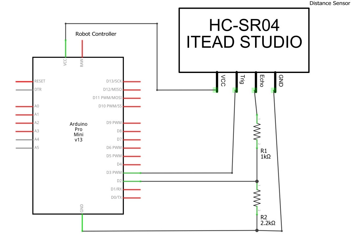
The Arduino Pro-Mini that I'm using to control the motors and sensors is a 3.3 volt device. Directly connecting a distance sensor to it would not end well. It might actually break the Arduino. There are special converter chips thatyou can buy to addressthis, but they are expensive and need to be wired up. Fortunately the only signals you need to worry about are those going into the Arduino, and the only input signal is the echo pulse. So I just have to adjust the level of that signal.
The way that the sensor works is that you give it a signal to say "please measure the distance". The sensor then makes an ultrasonic "squeak" and times how long it takes for the squeak to bounce back. It generates a pulse, called the echo signal that represents this time. The longer the echo pulse, the longer it took for the sound to bounce back, and the further away the target is from the sensor.
The echo signal provided by the distance sensor is either at 0 volts or 5 volts. We want to convert the 5 volt value to 3.3. I've used a potential divider to do this. This uses the principle that the voltages in a circuit are distributed according to the resistances in each element. The higher the resistance of one part of the circuit, the more volts are "dropped" across this part. This probably doesn't seem sensible, but it is how a lot of electronic devices work.
In the old days we used to use lots of low voltage bulbs in our Christmas lights. The mains voltage of 240 volts would be spread over, say 20 bulbs, each designed to work with 12 volts. All the bulbs were connected in a chain, so the voltage dropped across each bulb was 12 volts (a twentieth of 240). Bad news, if one of the bulbs fail the whole chain goes out.
Worse news, if a human being (who has a resistance a lot higher than a 12 volt bulb) puts themselves into the circuit trying to fix this they will find that nearly all the voltage is dropped across them, which is how until recently Christmas was always accompanied by grisly stories of people electrocuted when they were fixing the lights on their tree.
Anyhoo, back to the robot circuit. The total resistance of our two resistors is around 3K. The voltage dropped across the 1K resistor will be around the third of the 5 volt input. These are the volts I don't want. The voltage across the 2K resistor will be around two thirds of 5 volts, which is as near 3.3 volts as makes no difference. And it works, which is nice.
If you think about it, what I've made is a machine that can divide by 3 at close to the speed of light. Any signal going into the potential divider will be divided by 3 on the output because physics. The speed of these two resistors massively outperforms even the most powerful of digital computer, and so-called "analogue" computers like this were much used in the past.
