Oculus Quest 2 Headband

headband.png

If you are lucky enough to own and Oculus Quest 2 you will be enjoying the higher quality and lighter weight of the device compared to the first version of this device. However, you might have noticed that the head strap arrangement is a bit more primitive than the earlier version. One way to fix this would be to buy the expensive Elite Strap. Another approach is to print out a support that fits on the back of your head and holds the straps in place. I had a go at printing it and got the above result. I’m quite pleased with how well it came out. I used a very large layer height so that I got the strap quickly, which is why the quality is not the best. I also used “tree” support to hold up the large mid section. That worked really well too.

Use Quick Access to work with recent files

recent files.png

Now and again I fall over something so useful that I regret not having used it before. Such is the Quick Access feature of Windows 10. I found it by mistake and it is really rather nice. It lists the files that you have just been using. You might not think that is very useful, but if you remember that lots of applications, for example all the Office apps and programs like Cura, will open a file if you drag it onto them and drop it. You can also upload files to the wonderful OctoPi printer controller by just dropping them onto the browser page.

So when I want to take my saved design file from FreeCAD into Cura I just have to drag it out of the Recent files folder and drop it onto Cura. This saves a lot traipsing through file open dialogs. Now I keep the recent files folder open on the desktop just for things like these.

Pin numbers are not port numbers

esp8266 pins.png

In a blog post last month I confidently asserted that the output pins on an ESP8266 didn’t have enough “oomph” to drive the neopixels on an Adafruit 8x8 panel. I’m sure you remember the post.

Anyhoo, it turns out that the post (rather presciently titled “Making Mistakes”) was wrong. What I should have written is that if you use the wrong pin on your device it won’t work. Just because a pin is labelled D1 doesn’t mean that it is connected to GPIO1, as the diagram above makes very clear.

So now I can use an ESP8266 to drive my panel, which is nice.

Version control and the end of time

boom.png

The Timelords met, as Timelords do, from time to time for a coffee. And when they met they liked to talk about the old times and universes that have come and gone. “Ah, the earth universe” said one. “Indeed” said another. “I thought it had promise” said a third.

“The humans had discovered software and version control, and all was going reasonably well. And then one human decided to try to find out what happens if you put the name of the gitignore file into the gitignore file. And then their reality collapsed on itself. ”

The first timelord stared into his coffee cup. “If only they had known the true power of Git” he said glumly.

Consistency is key

height adjustment.png

I was quite proud of the height adjuster I made for Una my Ultimaker 3d printer. Although I wasn’t very proud of the way that I’d handled a lack of bolts of the correct length. Anyhoo, it seemed to work and allowed me to adjust the print head height just by turning the screw at the top. There was only one problem with it.

It didn’t work.

I could use it to move the switch up and down but it also moved the switch all by itself. There was too much play in the mechanism. I’d adjust the height carefully and then find that next time I homed the printer the height was all wrong again. Wah.

One of my favourite quotes is from Ralf Waldo Emerson and goes “A foolish consistency is the hobgoblin of little minds”. This is worth remembering when you are trying to make all the wires in your circuit the same length, or arrange your DVDs in alphabetic order and fretting about how the word “the” works in the movie title. However, when we are talking about things that only work if they are within a tenth of a mm of the correct position, I’m a big fan of consistency.

So it has been out with the fancy adjuster and back to the sturdy little bolts that fix the switch in one position. I’ve not got a bit more of a job to adjust the height of the print bed, but at least the adjustment will stick for a while.

The man who labels chutney

chutneylabels.png

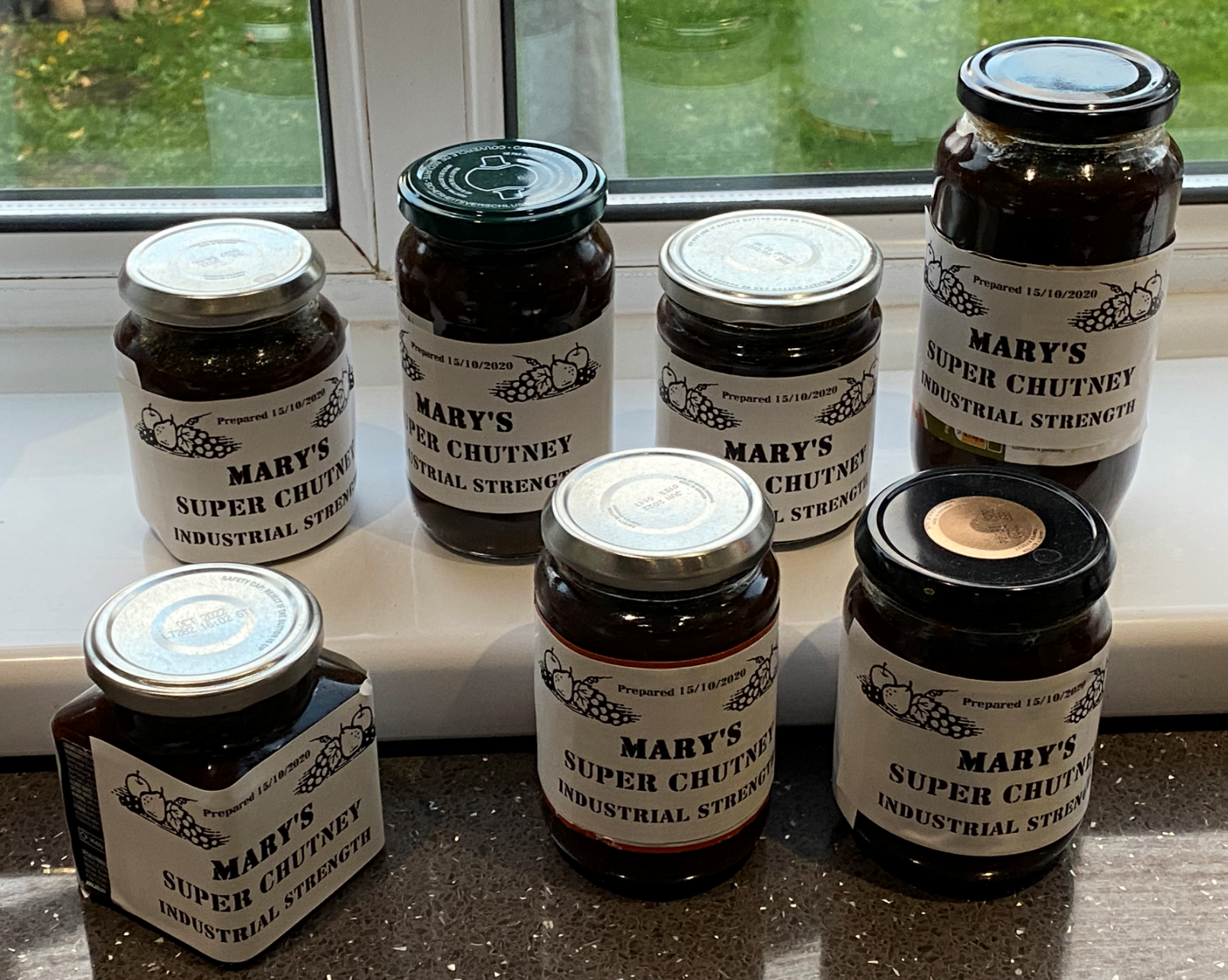
It doesn’t happen very often, but every now and then I find myself in the perfect position with just the technology that I need at my fingertips. It happened today. A while back number one wife came into possession of a large number of green tomatoes. Which screamed “chutney” to her and had the pleasing outcome of a number of differently shaped jars being filled with fabulous smelling stuff.

Today she asked me if I had any blank labels that she use for the jars. She was going to fill in each one by hand. “I can do better than that” I said and vanished upstairs for half an hour. A long while back I bought a label printer to liven up the entrant packs for Three Thing Game. So I happened to have a label printer and just enough labels to make the above. I’m rather pleased with the result.

Wide eyed and pinless

esp32 vroom.png

The ESP32 is mostly my weapon of choice when making embedded devices. The only problem that I’ve had with the device is that tends to be supplied as a device with ready soldered pins. This is fine if you want to plug it straight into a socket but I don’t tend to do that. I’m much happier soldering the wires directly onto the unit. This makes for a more reliable device and also allows me to use smaller boxes. T

The good news is that I’ve now found a supplier on AliExpress who is selling versions that don’t have the pins already fitted. They cost slightly more than the “normal” devices (which I find a bit surprising) but they do give a lot more flexibility.

One thing to remember though; it is a pain to build the ESP32 device into your device and then find that you have a faulty one. So make sure you test the ESP32 before you solder it in.

The power of the chamfer

freecad bevel.png

One of the problems that you can have when 3D printing is called the “elephant’s foot” problem. It is caused because the very first layer is usually printed very slowly and is very thick, causing it to spread out slightly. This leads to the side of the object having a profile that looks a bit like an elephants foot. Which I suppose explains the name…

I’ve found that one way to fix (or perhaps hide) this effect is to apply a “chamfer” to the printing face. This makes the first print layer slightly smaller and hides the foot effect. The chamfer is easy to perform in FreeCAD. You select the Part view in the Workbench and then select the chamfer option (it’s blue and looks like a chamfer (a corner with the edge flattened off). You can then select the face that of the object that you want to chamfer and you can get the rounded appearance you can see on the left hand shape in the design above. One day I’ll figure out how to do this from Python inside FreeCAD and then add it to the part design program.

chamfer.png

Then I print using a “brim” which is a bit of print around the outline of the object which helps it stick to the print bed. When the print has cooled I cut the brim off with some sharp scissors and this makes the edges look quite neat as you can see above.

Maketober Day 31: Christmas Cake to finish

cake.png

This is not actually something that I’m making. But I do get called in to give it a stir.

I’ve really enjoyed Maketober. Thanks to the folks at the Makerspace Hull for giving me the idea. It’s been very useful to have a focus on making (or at least achieving) something every day. I plan to keep on trying to deliver something useful each day and then write about it here. And I can’t wait until I’m able to go and show them what I’ve been making. And I might take along some cake too..

Makertober Day 29: Wiring up

wiredup.png

This is the completed light box, all wired up. I’ve printed a tiny little mounting plate that holds the ESP8266 device and allows it to be fitted onto the mounting pillars. I’m doing the wiring by soldering directly between the devices.

broken ring.png

I like using solid-core wire tor connections as it is easier to work with. But you have to be careful as it puts more strain on whatever it is connected to. Above you can see what happens when things go wrong. The solder pad for DI (data in) on the pixel ring has detached from the PCB and turned this ring into scrap. Fortunately I have a few spares.

fittingscrews.png

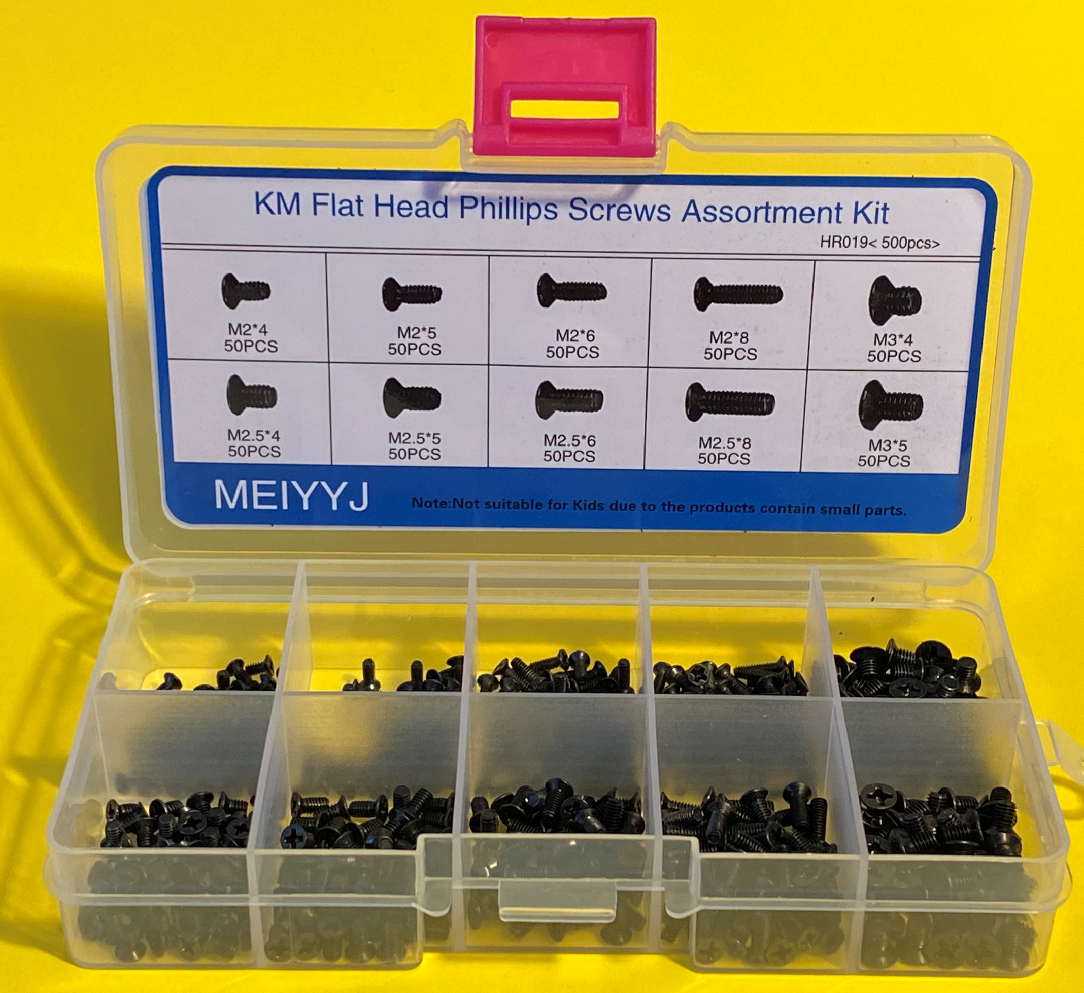
I’m fixing things together using tiny self-tapping screws. These can be hard to get hold of. I found this rather nice kit on Amazon for a reasonable price. The screws as supposed to be used when repairing laptops, but they work into 3D printed parts rather well. After a while I suppose I’ll use up all the screws of one particular size, but at least I’ll know which size to buy next time.

Makertober Day 28: Printing Boxes

Some people say that you shouldn’t use your 3D printer to make boxes for things. I disagree. Sure, a box is quite large and takes ages to print. But its not as if you have to spend that time yourself. Once you’ve set the printer off you can leave it to get on with it. Although I do still find the process fascinating to watch. Above you can see the output of my design which I think is fairly tidy. I could spend some time fiddling with settings to get the print better, but this is not actually something that the user will see.

shinyside.png

The reverse side, which is where the print was built up on my glass bed, is nicely shiny.

Makertober Day 27: Levelling your print bed

Yesterday I sorted out the printing temperature of my 3D printer. Today I’m going to spend some time on the other important aspect of 3d printer configuration: print height.

Una, my Ultimaker 3D printer is a “Fused Filament Fabrication” device. This is a posh way of saying that she “prints by squirting plastic onto a plate”. The distance the print nozzle from the plate is absolutely crucial. If the distance is too small you will get nothing because the plastic can’t get out of the nozzle. If the distance is too large you will get a ball of “plastic wool” because the plastic doesn’t stick to the plate and allow layers to build up. It’s also very important that the print head is the same height all over the bed, otherwise the plastic will stick in some places but not others.

bedlevelling.png

On Una you adjust the print height by moving the height limit switch up and down and then twiddling three screws to set the level of each corner of the bed. This is made much, much easier by a plugin I’ve found for the OctoPrint system that I use to send print jobs to the printer. You give this a bunch of locations and it moves the print head to each one in turn and lowers it down to the printing position. You can then adjust the height there and move on to the next one. Once you’ve been around the print area a few times you have got your print bed level. For my printer the correct height is when I can slide a sheet of paper underneath the print head and it just (and I mean just) catches the print head. I need to do this when the print head is at printing temperature.

I used to check the print height at positions all over the bed using a little height gauge but I’ve given up on that. My starting assumption is now that the bed is flat so that once the three points where it is supported are the right height the print height will be correct. If the print bed is not flat there’s not a lot I can do about it other than buy a new one anyway….

Makertober Day 26: Making heat tests

heattests.png

Now that I have something to print, the next thing I need is a working 3D printer. Oh well. Back into the fray. One of the factors that has a huge impact on the print quality you are going to get is the temperature of the print. So I’ve printed a bunch of tiny boxes to discover the optimal temperature. You can see the results above. It turns out that for optimal results with my printer I have to print at 215 degrees with a bed temperature or 60. If this sounds a bit high, you need to remember that the temperature is just the reading taken by the sensor in the head; not the actual temperature that the filament is being heated to.

In my print head the temperature sensor is right next to the heater which I think leads to higher readings. Anyhoo, from an engineering perspective any temperature that works is a good one.

Maketober Day 25: Making a light box

After a whole bunch of posts that have shown some creative uses of the word “make” but not actually described making anything, today I’ve actually made something. I’ve also done some time travel, going back to a program that I wrote quite a few years ago when I was designing boxes to put things in. I wanted to give the program a list of components and then have it turn out a box box for them. It worked especially well with the Microsoft Gadgeteer devices which were brilliant, wonderful and way ahead of their time.

def PirSensorBoxWemosWithPixelRing():
    print("Making PIR Sensor Box")
    proc = WEMOS("Wemos",verticalAlignment=VerticalAlignment.TOP, 
           horizontalAlignment=HorizontalAlignment.LEFT,xMargin=0.5, yMargin=0.5)
    holder = Device("blank", "blank", PixelRing.boardHeight, PixelRing.boardWidth,grid=[[proc]])
    lid1 = PIRSensorLidHole("PIRSensorLidHole")
    lid2 = PixelRingLightPipeLid("PixelRingLid")
    case = Case(wall_thickness=3,base_side_height=20,base_thickness=3.0,lid_side_height=5)
    case.makeParts([[holder]],[[lid1,lid2]])
    holeHeight=13
    holePos = Base.Vector((case.width-holeHeight)/2.0,case.height-1,-3.0)
    hole = Part.makeBox(holeHeight,4,8,holePos)
    case.baseDesign = case.baseDesign.cut(hole)
    case.show()

My box making system is written in Python and runs inside the FreeCAD tool. You can create component objects and then the system put them into boxes for you. The program works on pre-built software objects and has the ability to put components inside components. Above you can see the Python that makes a box that contains a PIR sensor, a 12 pixel neopixel ring and an ESP8266. The idea is that the will come on when you walk past the light. And, because the ESP8266 can do WiFi and other connected stuff I can make other lights come on too.

pirsensorbox.png

This is the output of the function. The ESP8266 is placed on the base of the box and the pixel ring and PIR sensor are fitted on the top. All I have to do now is print the boxes….

Maketober Day 24: Make a C++ class library for Arduino

robsSettings.png

Once you’ve written a bit of code you start to come up with libraries that you’d like to reuse in other projects. They might be things like drivers for particular pieces of hardware or useful storage or menu routines. If you are writing C++ code for your Arduino it turns out to be very easy to create library files. The Arduino development environment builds on what the C++ language uses to manage libraries.

It all hinges around the “library” folder in your Arduino installation. This is usually placed in the Arduino folder in your documents folder (as you can see above). You can also see that I’ve got lots of existing libraries. Every time I’ve downloaded a library it has ended up here. There is also a library file called Robs_Settings. That’s one that I made myself. If you have a look in this folder you will find the C++ source files that make it work:

settingfiles.png

For each library I have a .h file that contains definitions of the behaviours and a .cpp file that contains code. The idea is that a program that wants to use the library features will include the .h file so that it knows how to call the behaviours in the library. Then, when the program is built the compiler will find the .cpp file, compile the actual code and then all the different components will be linked together. When you start the compiler running you can tell it where to look for library files.

The Arduino environment knows the location of the library folder and will scan this folder when you open the “Include Library” option in the Sketch menu. It will show you any libraries that you have downloaded along with the one that we’ve just created.

arduino include.png

When I include the Robs_Settings library the Arduino environment scans the library folder and creates an include statement for each of the .h files that it finds in the folder:

included libraries.png

If you compare the code above with the contents of the settings folder you will see how this works. Now you can use any of the code in the library in your application.

Note: You might think that just adding the include directives above would make it possible for your program to use the included files. This is not so. The Arduino IDE does some behind the scenes shenanigans to link these includes to your library which will result in you getting errors when you build the program.


Maketober Day 23: Make a good book purchase

nature of code.png

There are two reasons why I wish I’d written The Nature of Code by Daniel Shiffman. The first is that it is really nicely put together and covers a whole range of useful topics in a very readable style. It’s really a book to be proud of. The second reason I wish I’d written it is that if I had I’d know all the content. Which I don’t - yet.

I think it would be especially useful to game developers as it covers a whole bunch of topics that you can use to make your code more organic and interesting.

All the programming examples are written using the Proccesing language. Don’t let this put you off. Processing has a lot in common with Java and JavaScript and the techniques can all be mapped over to these and other languages. I made a purchase of the book today. Strongly recommended.

Maketober Day 22: Make Life Easier with Microsoft PowerToys Fancy Zones

powertoys.png

I recently got a much larger monitor. Part of this was driven by a desire to see more of the world when flying with Flight Simulator, but also because I thought it might make me more productive. If it worked I my plan was to buy a video projector and paint the wall white..

Anyhoo, the new screen is jolly nice, but window management can be a pane (pun intended). Enter Microsoft PowerToys. Among a bunch of useful things is the very useful Fancy Windows utility. This lets you configure a set of zones onto your screen. You can then move windows into those zones by holding down the SHIFT character while dragging. This makes it really easy to spread things over your display. There are other ways you can push applications onto the zones but I like using the Shift key.

I’d say that just Fancy Zones was totally worth the price of admission to PowerToys, but as they are a free download this would be a silly point to make. The only tiny snag that I’ve found is that the tools work best when running as Administrator and can be a bit of a faff. However, I reckon the tools are totally worth the effort.