FreeCad Simulator is now on GitHub

FakeFreeCad.png

I’ve made this horrible hack to make it easier to debug my Python macros that run inside FreeCad and design little boxes. It means that I can use all the lovely debugging features of Visual Studio Code to find out why my code don’t work. The hack takes the form of a few simple Python objects that fake part of the FreeCad ones and allows your macros to run in any Python environment you fancy.

If you like the idea of writing Python code that produces physical artefacts you might want to take a look at it. You can find it on GitHub here.

Oculus Quest 2 Headband

headband.png

If you are lucky enough to own and Oculus Quest 2 you will be enjoying the higher quality and lighter weight of the device compared to the first version of this device. However, you might have noticed that the head strap arrangement is a bit more primitive than the earlier version. One way to fix this would be to buy the expensive Elite Strap. Another approach is to print out a support that fits on the back of your head and holds the straps in place. I had a go at printing it and got the above result. I’m quite pleased with how well it came out. I used a very large layer height so that I got the strap quickly, which is why the quality is not the best. I also used “tree” support to hold up the large mid section. That worked really well too.

Consistency is key

height adjustment.png

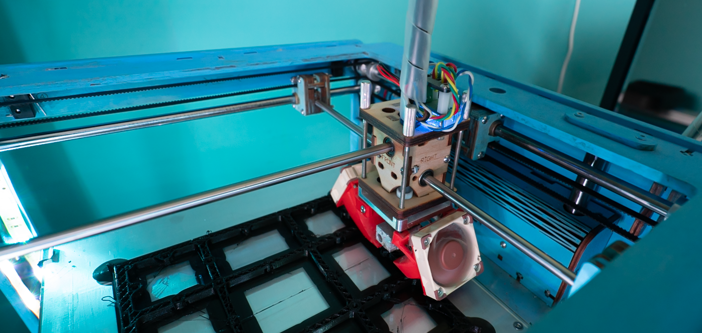
I was quite proud of the height adjuster I made for Una my Ultimaker 3d printer. Although I wasn’t very proud of the way that I’d handled a lack of bolts of the correct length. Anyhoo, it seemed to work and allowed me to adjust the print head height just by turning the screw at the top. There was only one problem with it.

It didn’t work.

I could use it to move the switch up and down but it also moved the switch all by itself. There was too much play in the mechanism. I’d adjust the height carefully and then find that next time I homed the printer the height was all wrong again. Wah.

One of my favourite quotes is from Ralf Waldo Emerson and goes “A foolish consistency is the hobgoblin of little minds”. This is worth remembering when you are trying to make all the wires in your circuit the same length, or arrange your DVDs in alphabetic order and fretting about how the word “the” works in the movie title. However, when we are talking about things that only work if they are within a tenth of a mm of the correct position, I’m a big fan of consistency.

So it has been out with the fancy adjuster and back to the sturdy little bolts that fix the switch in one position. I’ve not got a bit more of a job to adjust the height of the print bed, but at least the adjustment will stick for a while.

The power of the chamfer

freecad bevel.png

One of the problems that you can have when 3D printing is called the “elephant’s foot” problem. It is caused because the very first layer is usually printed very slowly and is very thick, causing it to spread out slightly. This leads to the side of the object having a profile that looks a bit like an elephants foot. Which I suppose explains the name…

I’ve found that one way to fix (or perhaps hide) this effect is to apply a “chamfer” to the printing face. This makes the first print layer slightly smaller and hides the foot effect. The chamfer is easy to perform in FreeCAD. You select the Part view in the Workbench and then select the chamfer option (it’s blue and looks like a chamfer (a corner with the edge flattened off). You can then select the face that of the object that you want to chamfer and you can get the rounded appearance you can see on the left hand shape in the design above. One day I’ll figure out how to do this from Python inside FreeCAD and then add it to the part design program.

chamfer.png

Then I print using a “brim” which is a bit of print around the outline of the object which helps it stick to the print bed. When the print has cooled I cut the brim off with some sharp scissors and this makes the edges look quite neat as you can see above.

Makertober Day 29: Wiring up

wiredup.png

This is the completed light box, all wired up. I’ve printed a tiny little mounting plate that holds the ESP8266 device and allows it to be fitted onto the mounting pillars. I’m doing the wiring by soldering directly between the devices.

broken ring.png

I like using solid-core wire tor connections as it is easier to work with. But you have to be careful as it puts more strain on whatever it is connected to. Above you can see what happens when things go wrong. The solder pad for DI (data in) on the pixel ring has detached from the PCB and turned this ring into scrap. Fortunately I have a few spares.

fittingscrews.png

I’m fixing things together using tiny self-tapping screws. These can be hard to get hold of. I found this rather nice kit on Amazon for a reasonable price. The screws as supposed to be used when repairing laptops, but they work into 3D printed parts rather well. After a while I suppose I’ll use up all the screws of one particular size, but at least I’ll know which size to buy next time.

Makertober Day 28: Printing Boxes

Some people say that you shouldn’t use your 3D printer to make boxes for things. I disagree. Sure, a box is quite large and takes ages to print. But its not as if you have to spend that time yourself. Once you’ve set the printer off you can leave it to get on with it. Although I do still find the process fascinating to watch. Above you can see the output of my design which I think is fairly tidy. I could spend some time fiddling with settings to get the print better, but this is not actually something that the user will see.

shinyside.png

The reverse side, which is where the print was built up on my glass bed, is nicely shiny.

Makertober Day 26: Making heat tests

heattests.png

Now that I have something to print, the next thing I need is a working 3D printer. Oh well. Back into the fray. One of the factors that has a huge impact on the print quality you are going to get is the temperature of the print. So I’ve printed a bunch of tiny boxes to discover the optimal temperature. You can see the results above. It turns out that for optimal results with my printer I have to print at 215 degrees with a bed temperature or 60. If this sounds a bit high, you need to remember that the temperature is just the reading taken by the sensor in the head; not the actual temperature that the filament is being heated to.

In my print head the temperature sensor is right next to the heater which I think leads to higher readings. Anyhoo, from an engineering perspective any temperature that works is a good one.

Maketober Day 25: Making a light box

After a whole bunch of posts that have shown some creative uses of the word “make” but not actually described making anything, today I’ve actually made something. I’ve also done some time travel, going back to a program that I wrote quite a few years ago when I was designing boxes to put things in. I wanted to give the program a list of components and then have it turn out a box box for them. It worked especially well with the Microsoft Gadgeteer devices which were brilliant, wonderful and way ahead of their time.

def PirSensorBoxWemosWithPixelRing():
    print("Making PIR Sensor Box")
    proc = WEMOS("Wemos",verticalAlignment=VerticalAlignment.TOP, 
           horizontalAlignment=HorizontalAlignment.LEFT,xMargin=0.5, yMargin=0.5)
    holder = Device("blank", "blank", PixelRing.boardHeight, PixelRing.boardWidth,grid=[[proc]])
    lid1 = PIRSensorLidHole("PIRSensorLidHole")
    lid2 = PixelRingLightPipeLid("PixelRingLid")
    case = Case(wall_thickness=3,base_side_height=20,base_thickness=3.0,lid_side_height=5)
    case.makeParts([[holder]],[[lid1,lid2]])
    holeHeight=13
    holePos = Base.Vector((case.width-holeHeight)/2.0,case.height-1,-3.0)
    hole = Part.makeBox(holeHeight,4,8,holePos)
    case.baseDesign = case.baseDesign.cut(hole)
    case.show()

My box making system is written in Python and runs inside the FreeCAD tool. You can create component objects and then the system put them into boxes for you. The program works on pre-built software objects and has the ability to put components inside components. Above you can see the Python that makes a box that contains a PIR sensor, a 12 pixel neopixel ring and an ESP8266. The idea is that the will come on when you walk past the light. And, because the ESP8266 can do WiFi and other connected stuff I can make other lights come on too.

pirsensorbox.png

This is the output of the function. The ESP8266 is placed on the base of the box and the pixel ring and PIR sensor are fitted on the top. All I have to do now is print the boxes….

Makertober Day 18: Making a working printer

backprintng.png

I think you should all know that the little plastic rocket above was the product of a lot of effort today. In the end I discovered that last time I mended the printer I’d left a tiny gap between two parts of the path into the print head. If the plastic in this gap melted it then formed a plug which blocked everything up. All I had to do was take the printer to pieces, put it back together wrongly a couple of times and then finally get it right.

So I know have a 3D printer that works. As far as I know.

Maketober Day 17: Making a broken printer

printerbits.png

Una my lovely 3D printer is what I call a “Schrodinger Device”. She’s got this title in honour of the celebrated “thought experiment” involving a box containing a cat and something that might, or might not, kill the cat. The idea is that right up until you open the box and take a look inside you don’t know whether the cat is dead or not. From a quantum perspective you can regard the cat as both dead and alive until you find out what has happened. The same kind of thing happens with Una. At any given time I may or may not have a working 3D printer. I only find out which is true when I try to print something. I’ve owned many such devices in the past, including a Mini Traveller that sometimes was a car and sometimes wasn’t.

Anyhoo, today when I tried to print a box for a LED panel that I’ve been playing with I discovered that Una is no longer a printer. I’ve spent most of the day proving that this fact is most definitely true. In this time I’ve replaced some bits, recalibrated others and cursed all of them. Oh well.

Still supported after all these years....

I’m not sure many companies are still providing support for eight year old products. Apple make a big song and dance about how they provide updates for their phones for “at least five years” after manufacture (which I think is a bit rubbish bearing in mind how much they cost). I find it amazing that tech companies are allowed to get away with this. Nobody else (for example car makers) is allowed to call time on their products in this way.

Anyhoo, rant over. Today I contacted Ultimaker about replacement bits for Una, my printer. I’ve found some things on Ali-Express which look like they might fit, but they have a twenty day delivery (if I’m lucky) and so I thought I’d go back to the source. They put me onto their UK dealer who had the parts I need in stock and they are in the post. Should arrive tomorrow. Awesome.

Una has fallen...

broken una.png

Una, my Ultimaker original 3D printer, has been happily printing out bits and bobs for the last week or so, although I have been needing to use higher and higher printing temperatures to get a decent flow of material through the print head. Not a thing that should be happening on the way into summer. Anyhoo, today I set her off as usual and went back to check on progress, only to discover that she had been waving her print head around for an hour or so, printing nothing.

So, I took everything to bits to discover that the filament had melted into the end of the Bowden tube (the tube that delivers the filament to the print head). This has produced a pretty solid blockage which is not going anywhere in a hurry. I think it was caused by the little PTFE fitting (the white bit in the picture above) wearing out and collapsing.

So, no more 3D printing for a while. I’m going to have to track down some spares.

Making trivets

I love the way that 3D printing lets you go from an idea to a thing really quickly. Thanks to a what seems to be a worldwide shortage of liquid soap (I wonder why that might be) we now have a soap-powered cleanliness routine. This has led to a need for soap dishes. We’ve re-purposed a bunch of little dishes, but we have the problem of the soap getting wet and icky (and dissolving) in the dish when it gets wet.

We needed something to keep the soap out of the water that runs off it after use. A kind of “soap trivet” that fits in the bottom of the soap dish. A few minutes with OpenSCAD and I had my design. A little while later we had our printed trivets. And now Una can go back to making PPE visors.

If you have a need for a soap trivet, you can find the OpenSCAD code here.

Printing Visors for Covid-19

I noticed that Paul was printing out visor holders for health workers. I thought I’d like to have a go and he was kind enough to send me his design of choice. Of course Una (my 3D printer) promptly decided to play up massively. At one stage I resorted to shouting “I’m trying to do something good here!” very loudly at her. That didn’t work and so I replaced the print nozzle for one that actually had a hole in it.

This improved matters considerably, and after a couple of hours I had my first prototype. You are supposed to use A4 plastic binder covers but, not surprisingly, these are a bit hard to get hold of at the moment.

I’ve ordered a bunch, but for now I’m making do with some transparency film that I had lying around for printing out overhead projector slides (remember them). I’ve also ordered some proper length elastic bands.

The finished article looks OK to me. I’m going to wear it for a while just to see how long it lasts. Now all I need to find is someone who wants a mask like this. I’m not saying it is perfect, but it beats the heck out of nothing…..

If you have such a need, let me know