Old age coping strategies
/
I got some slippers for Christmas. I really like the way that they look like proper shoes. Now I just need some pyjamas that look like jeans and a sweatshirt and I’ll be perfectly equipped for old age.
I got some slippers for Christmas. I really like the way that they look like proper shoes. Now I just need some pyjamas that look like jeans and a sweatshirt and I’ll be perfectly equipped for old age.
In the last post we saw how easy it is to make an ESP32 processor sleep for a particular time. However, we also noticed that at the end of the sleep the processor is reset and all the variables in the program are reset. This is difficult if you want to keep track of time in your application. However, it is possible to get around this limitation by storing a time value in memory that is retained during sleep.
RTC_DATA_ATTR unsigned long millisOffset=0;The statement above declares a variable called millisOffset. The attribute RTC_DATA_ATTR tells the compiler that the variable should be stored in the real time clock data area. This is a small area of storage in the ESP32 processor that is part of the Real Time Clock. This means that the value will be set to zero when the ESP32 first powers up but will retain its value after a deep sleep.
We can use this variable to create an offsetMillis function that gives a millisecond count which is adjusted by the offset:
unsigned long offsetMillis()
{
    return millis() + millisOffset;
}
Our program is going to call this function when it wants to know how much time has elapsed since the application was started. The final part of the solution is to update the offset each time our processor is put to sleep.
void sleepSensor(unsigned long sleepMillis)
{
    esp_sleep_enable_timer_wakeup(sleepMillis * uS_TO_mS_FACTOR);

    millisOffset = offsetMillis() + sleepMillis;

    esp_deep_sleep_start();
}
Now, when our application goes to sleep it records the value that the millisecond timer should have when the device wakes from sleep. This value is retained in non-volatile memory and used to offset time values when the ESP32 restarts.
#include <Arduino.h>

RTC_DATA_ATTR unsigned long millisOffset = 0;

unsigned long offsetMillis()
{
    return millis() + millisOffset;
}

#define uS_TO_mS_FACTOR 1000  /* Conversion factor for micro seconds to miliseconds */

void sleepSensor(unsigned long sleepMillis)
{
    esp_sleep_enable_timer_wakeup(sleepMillis * uS_TO_mS_FACTOR);

    millisOffset = offsetMillis() + sleepMillis;

    esp_deep_sleep_start();
}

void printTime()
{
    unsigned long seconds, sec, min, hrs;

    seconds = offsetMillis() / 1000;

    sec = seconds % 60;
    seconds /= 60;
    min = seconds % 60;
    seconds /= 60;
    hrs = seconds % 24;

    Serial.printf("%02d:%02d:%02d\n", hrs, min, sec);
}


void setup() {
    Serial.begin(115200);
    printTime();
    sleepSensor(30000);
}

void loop() {
}
The complete program above shows how it all fits together. The program sleeps the device for 30 seconds but the time value is maintained after each reset. Note that the loop function is empty because the program never gets this far. The repeating behaviour of the program is caused by the reset after each sleep.
I was quite surprised just how poor the time keeping is when I ran this program. This is because the timing is not provided by a crystal but by an oscillator which is fitted onto the ESP32 chip. The timing can be out by a second or so over short intervals. Try timing the above program to see what I mean.
The millis function in the Arduino library returns an unsigned long integer value that holds the number of milliseconds since a device was turned on. The program above works by adding an offset to this millis value which reflects how long the device has been put to sleep. Of course, what with data storage in any computer being a finite size, there will come a point where the millis value will not fit in an unsigned long variable and so it will wrap round and go back to 0. This occurs after 4,294,967,295 milliseconds or around 50 days. If your program does any kind of calculation with the timing values you will need to make sure that the wrap round doesn’t cause problems.
I'm very proud of the picture above. It shows that I'm getting around 0.1ma current consumption on our new environmental sensor when it is in deep sleep mode.
It's very easy to put an ESP 32 into deep sleep mode. This is the code that I'm using:
#define uS_TO_mS_FACTOR 1000  /* Conversion factor for micro seconds to miliseconds */

void sleepSensor(unsigned long sleepMillis)
{
    esp_sleep_enable_timer_wakeup(sleepMillis * uS_TO_mS_FACTOR);

    esp_deep_sleep_start();
}
The sleepSensor function is called with a parameter that gives the number of milliseconds for the sleep duration. It sets up a timer wakeup for that duration and then starts the deep sleep process.
The functions esp_sleep_enable_timer_wakeup and esp_deep_sleep_start are in the ESP32 library that is added to your program when you select a device based on the ESP32 processor. If you want to use them you have to include the Arduiono libraries by putting this statement at the start of your program:
#include <Arduino.h>When the ESP32 "wakes up" at the end of the sleep the processor is restarted. The timing of the sleep duration is not particularly accurate, certainly not as accurate as the internal clock you get when the ESP 32 is running. You can make the wakeup trigger a button press rather than a timeout if you wish.
When an ESP 32 is restarted after a sleep all the varaibles are re-initialised. However, there is a way that your application can preserve some variable values in Real Time Clock memory. More of this later.
Last time, in the post here we discovered how the __FILE__ and __LINE__ symbols make it possible for a program to print out a tracing information. This can be very useful if, as is the case with Arduino development, there is no easy way to step through your code. The problem that we now have is that we need to add calls to the trace method, and we will have to remove them later.
show_location(__FILE__, __LINE__);
However, there is another feature of the C compiler that we can use which makes it very easy to add and remove debugging statements. This feature is provided by the C compiler pre-processor. The pre-processor, as the name implies, is the part of the compiler that takes in the source code file and can do some processing on the program text. Commands to the pre-processor are pre-ceded by the # character.
One pre-processor directive (something we use to tell the pre-processor what to do) is #define, which defines a symbol. If we get bored with typing lots of digits of PI (3.141592654) we can use #define to tell the pre-processor to do the hard work for us.
#define PI 3.141592654
Now, whenever the pre-processor sees the symbol PI it will replace it with the digit sequence. So, consider if my program contained the following statement (assuming I have variables called circ and rad declared somewhere):
circ = rad * 2 * PI;
The symbol PI is replaced by the number sequence that it was defined with, so that the circumference of the circle is calculated using the value of PI as defined.
The #define pre-processor directive is really powerful, and should probably come with some warnings. Here are a few:
There is nothing to stop a silly programmer re-defining the value of the PI symbol at any point in your program. They could define it as 4 which would cause your program to produce the wrong results, or they could define it as “chicken” which would cause your program to produce some very interesting compilation errors as your program was now trying to use the word “chicken” in arithmetic statements.
The defined symbol must be an identifier that “makes sense” in C. There is a convention that #defined symbols are given names that are in all capitals, with words separated by underscore so that they stand out in your code
The pre-processor does not replace defined symbols inside strings. In other words the statement:
Serial.println(“Have some PI”);
- just prints the message “Have some PI”. However, you can use #define to create symbols that are complete strings:
#define WELCOME_MESSAGE “Hello”
I can now write:
Serial.println(WELCOME_MESSAGE);
I regard the #define statement as strong magic. I do all my #defines in one place in each source file and I only use them sparingly.
Anyhoo, back to how to use #define to make our lives easier. We can save typing by replacing the call of the show_location with #define symbol:
#define TRACE show_location(__FILE__, __LINE__)
Now, when I want to produce trace output to show where the program has reached I can just use the TRACE statement:
TRACE ;
The pre-processor will extend this and enter the text of a call of the show_location method.
It gets better. If I want to turn off all the trace statements I can just remove the TRACE symbol from my program by defining it as an empty string:
#define TRACE
This means that the pre-processor will now replace the symbol TRACE with nothing so that the trace statements are no longer present in the source of the code. A program can re-define a symbol as it is compiled, so you can enable and disable the trace behaviour in different parts of the code if you like.
The post for today would have been the second instalment of the Arduino debugging series, but since the Squarespace web based editor has decided that the penalty for clicking outside the post edit window is to have the entire post instantly discarded (thereby removing an hour of writing) you are going to have to make do with this minor rant.
This book is a fun read. There’s some really nice science in with the absurd questions, along with the quirky illustrations that Randall Munroe is so good at. I got it at a very good price. And mine is signed too.
A long time ago I wondered about getting a blowlamp and selling singed copies of my books.
Is it wrong to buy your wife a box of chocolates for Christmas with the intention of using the empty chocolate box for a hardware project? Oh, and is it also wrong to get impatient when she takes her time eating the chocolates and making the box available?
Asking for a friend.
Why not have a mini-sequence of posts about Arduino debugging. Why not indeed?
Let’s start with a consideration of why the Arduino is hard to debug. The main reason is that you have no idea what is going in inside your code. If you’re writing a program on a computer with a keyboard and screen you can use any number of tools to find out what broke. There are debugging tools in Visual Studio that let you watch your program statements run one at a time and view (and even change) the values held in program variables.
The Arduino device has nothing like this. If you want to find out where your program has reached you have to put your own debugging statements. You end up writing things like this:
Serial.println(“I got this far”);
This prints out a message to the serial port tell us how far the program got. If you use the Arduino serial monitor you can view this message and know that at least the program has got this far.
This works and can be very useful. Developers call it “code instrumentation”. However, these messages can get confusing if you lots of them. What I’d really like to know is which line in the code that the program has got to. Then I can look this up in the source file. Turns out that this is quite easy. The compiler maintains two symbols called __FILE__ and __LINE__ which hold the name of the source file and the line number at that point in the program source.
So you can print this information out in your code:
Serial.print("Program is in file ");
Serial.print( __FILE__);
Serial.print(" at line " );
Serial.println(__LINE__);
These statements will tell you exactly where you have got to:
Program is in file C:\Users\Rob\Documents\Arduino\blah\blah.ino at line 12
This works well, but we can make it easier to use by putting the behaviour into a function:
void show_location(char * file, int line)
{
Serial.print("Program is in file ");
Serial.print(file);
Serial.print(" at line " );
Serial.println(line);
}
Now we can find out where our program has got to by just calling this function and passing the file and line values:
show_location(__FILE__, __LINE__);
We can now drop calls of show_location in our program to tell us exactly where the program has got to.
Of course, we have a problem in that we have to go and remove all these statements when we have finished debugging, but tomorrow I’ll show you how to make this easy too.
So I’m testing the NeoPixel drivers of an ESP32 board that Brian has designed. Everything works fine, except that the first pixel in the chain of pixels is always green.
I’m OK with green in general. I can’t imagine grass being any other colour. However, I prefer it not to show up when my program is trying to display other colours.
So… I spent quite a long time trying to work out how my code could be doing this. Was a rogue routine setting my first pixel green every now and then? Was my understanding of RGB more GRB? Nope. Everything worked. Which was annoying.
After a while I decided go search for “first neopixel is always green” and it turns out that this is a thing. This is one of these bugs that not only shouldn’t happen, but also I can’t work out how it could happen.
Anyhoo, I switched from the Adafruit neopixel drivers to the FastLed ones and the problem went away. Hardware development is like this. Sometimes you end up reconciling yourself to the fact that you have to do things that you don’t really understand simply to get the thing to work.
Went to the dentist today. Reminded of my favourite dentist joke:
“That’s a very big cavity .. cavity .. cavity……”
Yesterday I ordered the panels for my LED cube. Today I find out that number one son has got a set for quite a bit less money from a different supplier. This should not annoy me. It is not as if the price I paid was too high, and I can afford it. However, it does annoy me. Does this make me a bad person?
We’re taking our first steps in building a LED cube. I dug out some of my old panels and we tried running them from a Raspberry Pi 4 with the Adafruit LED Panel Bonnet. We made the tweak described here to use the Raspberry Pi sound hardware to generate some of the display waveforms. This improves display stability at the price of disabling sound output from the Pi. This seems a trade well worth making, in that after the update the panel display was glitch free.
The led panels are interesting. I’ve used them with an ESP32 in the past. The way that the hardware works, only one in 32 rows of pixels are turned on at any given time. The host device must repeatedly light up all the pixels in sequence. It gets even more tricky if you want to control the brightness of individual pixels as this must be performed using pulse width modulation of the multiplexed display.
The word on the street is that a Raspberry Pi 4 can drive 6 panels of 64x64 pixels. We’ve not gone beyond 3 panels of 32x32, but we are hopeful.
Next step is to order the panels….
Spent some of my Christmas money (yes, I still get Christmas money - thanks folks) on this amazing Lego Dinosaur kit which is now gracing our mantelpiece. Very nice.
Not sure what I’m going to do with 100 cards with cheesy jokes on them. But I’m sure I’ll think of something…..
Almost makes me wish I was still giving lectures.
We had our first board game session of the year tonight. We believe in starting early. Simon came around and brought a copy of Clank! with him. It’s a deck building game where you move around a dungeon with the aim of collecting valuable artefacts and making it out alive. But make sure that you move quietly because every “clank” that you make could wake the dragon, something which never ends well. It’s great fun with lots of tension at the very end of the game as you struggle to get above ground with your hard won treasure.
Another family tradition is a trip to Hornsea on New Year’s Day. And a bacon buttie at the Floral Hall.
I’m happy to report that these passed off well again this year. And I took the proper camera.
Happy New Year to both my readers.
Christmas with all the family around. What better time for the dishwasher to go wrong? It still washes fine, but the trays of dishes have a habit of dropping off their support rails and plunging into the bottom of the machine when you load it.
Fortunately, I’m a lot better at repairing dishwashers than music players. A quick search of the internets revealed that it is very easy to get replacements for the wheels on the bottom of the tray. These had worn to the point of extreme wonkiness. The ones I found were identical to the originals and a lot less wonky. Result.
Today finds us in Ikea eyeing up their Tradfri home automation devices. A year ago I bought some very cheap Teckin remote controlled plugs. I hooked these up to Amazon echo buttons so that I could turn all my lights on and off with a single press (of different buttons unfortunately but nothing is perfect).
They work fine, but the plugs use WiFi and I was a bit nervous about having my lighting controlled by a server in China. So today I went in search of something a bit better. The interesting news is that it seems to be possible to re-flash my plugs to allow them to be controlled locally via MQTT, but that is a project for another day.
After a bit of pondering I went home with a bunch of smart sockets, some bulbs, a gateway and two remote controls. And a bookcase, but that is just because when you’re in Ikea you have to buy a bookcase.
Anyhoo, this evening I set them up. It went smoothly enough. The smart devices use Zigbee to communicate. If you want you can work with just bulbs and Ikea remote controls. You pair one or more devices with a single remote control so that it is very easy to control a bunch of devices from one button. You can add a gateway that links Zigbee to your home network, and this is when things get interesting. There’s a Tradfri app that you can install on your phone that lets you group devices and control them all at once too.
This is quite good, but what I did was use Apple HomeKit (which Tradfri is compatible with) to set up all my home automation once I’d got the lights working. This lets you create “scenes” involving all your devices. The scenes can be selected from your phone or watch and you can also create automations that are are triggered by events such as sunrise, sunset, arriving home etc. It’s great fun and maybe even useful. Things I’ve learned:
You need at least one Tradfri remote control to perform the setup of devices. All the devices setup by a particular remote will be controlled by that remote.
Once you move into the HomeKit domain the distinction of devices and remotes vanishes, and you can combine any or all of your devices into scenes as you see fit.
Once you’ve set your lights to work with HomeKit you don’t need the Ikea remotes at all.
Your devices have different names on HomeKit and Tradfri, although you can change them to match up.
It is actually quite cool to be able to control your lights from your watch.
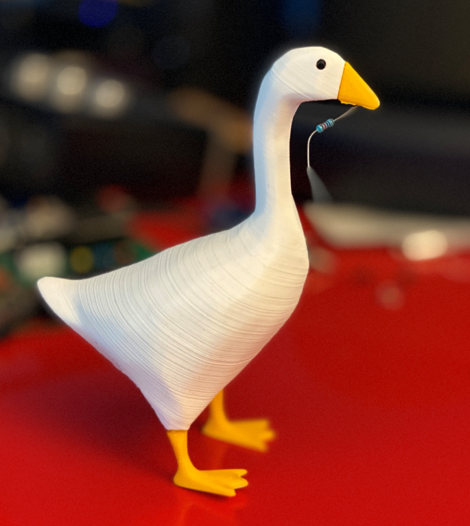
If you’ve got an Xbox Game Pass you play Untitled Goose Game for free. And you should. You take the role of an annoying goose with a mission to cause havoc. The pace is nice and gentle and the animation and drawing is really well done.
And number one son has found a design on Thingiverse to print our very own goose models. You can see my first effort above. I need to work on the layering a bit but overall I’m very pleased with the results. You can fit a magnet into the beak so that your goose can hold little metal objects.
The design supplied in for the white, yellow/orange and black parts. We’ve found that ordinary “superglue” (cyano-acrylate) does a good job of holding the parts together.
My goose has a slightly rakish stance because he fell off the desk and broke his foot off which I had to glue back.
I now have a ruler that will run Python. My life is complete……
Actually it is quite useful. Probably. You can program it to show up as a keyboard device and you can get your program generate keypresses when you touch the panels. The default settings are as shown above, but I’m going to make it generate the backslash character which I always have difficultly finding thanks to my liking for American keyboards.
It runs Circuit Python which means that you can just drop your code into the usb drive it mounts when connected. The only thing I don’t like is that you have to plug the ruler into an external power supply to get it to work. If it had a little battery it would be perfect.
Rob Miles is technology author and educator who spent many years as a lecturer in Computer Science at the University of Hull. He is also a Microsoft Developer Technologies MVP. He is into technology, teaching and photography. He is the author of the World Famous C# Yellow Book and almost as handsome as he thinks he is.
Begin to Code with JavaScript is now available for purchase and download. You can find it here