Using the Second Serial Port on the ESP8266

Wemos Printer .png

The ESP8266 processor chip has one and a half serial ports. One has both TX and RX connections, so that it can both send out data and listen for incoming data. This is port usually connected to via USB to the host computer and used to send programs into the device and to have conversations with our running programs. We can use this port to connect to other things but this makes it hard to interact with our device.

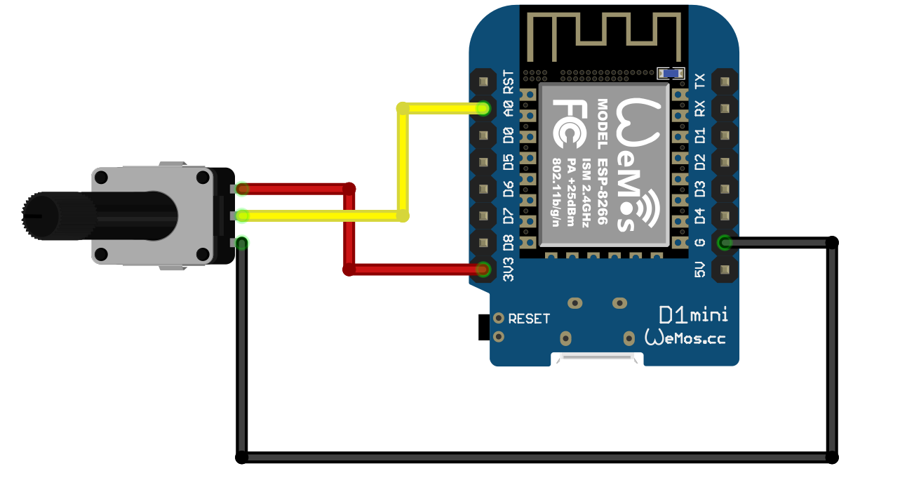
The other “half serial port” on the ESP8266 is a port that can only transmit data. That’s fine for me at the moment as I only want to send data to a printer. The TX signal for this port is connected to D2 on the ESP8266 and which is wired to pin D4 On the WEMOS D1 Mini, as shown in the diagram above. For numbering reasons (computer people like to start counting at zero) the second printer port is numbered Serial1. You can open and use it in the same way as the other port:

Serial1.begin(19200); // open the port at 19200 baud
Serial1.println(“hello”);

Your program can try to read from this port, but it won’t see any data.

What about SoftwareSerial?

At this point you might be asking “Why doesn’t Rob just create a software serial port and have done with it?”. Good question. A software serial port is a piece of code that twiddles a data output as if it was being driven by serial port hardware. This is called “bit bashing” because the code “bashes” the data out.

The only problem with a software serial port is that it usually requires the sole attention of the processor when it s being used. I thought when I first saw these that they might do cunning things with timers and interrupts that meant that they had no impact on performance, but this is not the case. If you use SoftwareSerial you will find that your program is effectively stopped while it sends and reads data. That might be OK for you, but not for Rob. I don’t want the lights on my Connected Little Box device to flicker when it prints something. So I much prefer a physical port which sends each byte of data without the involvement of the processor.

Rob’s Amazing Interrupt Driven Serial Port

On a slightly different topic, if you need to connect a very large number of serial ports to an ESP8266 device and you don’t want to use Software Serial to read them all (which usually doesn’t work if you have more than a couple of inputs) you might like to take a look at my “edge triggered serial port” code here. This is a Software Serial implementation that only stops the processor when it sees the edges of serial data.

It's still always the power supply

printertest.jpg

In a post a while back I surmised that if weird things are happening it is because of a problem with the power supply. It’s still true.

I’ve decided to add a printer to my Connected Little Boxes. I thought it might be fun to be able to print little messages on paper. I dug out my little printer and connected it a Wemos device. I did a tiny test and it worked fine. So I set to and built a printer module into the Connected Little Boxes framework. And it didn’t work. That’s not actually surprising. I’m deeply suspicious of code that works first time. It usually means that I am due a bunch of pain further down the tracks. This time it looked like I was getting all my pain up front, which is fine with me as long as I can fix it.

I did some tests and it looked like a buffer/timing problem. Short strings printed fine. I could print“12345678” but if I tried to print “123456789” it failed. The buffers were all the right size, the logging said the printing had completed OK. The little lights that I had connected to the printer data signals all flickered hopefully. The only thing missing was printed output. Wah.

I did what I usually do when I hit a problem like this. I went and had a cup of tea. I’ve discovered that if you hit a problem where the universe seems to be broken the best thing to do is walk away from it for a while. I’m lucky in that I haven’t actually got a customer waiting impatiently for the product and the printing feature is not the subject of a piece of my coursework that is due in (the other reason for fretting about deadlines).

After my second biscuit I’d figured it out. It was my old nemesis the power supply. The printer I’m using is thermal and prints a line of text all at once. The more you print the more paper it has to heat up and the more power it needs. I was powering it from the USB connection on my PC which can’t deliver much current. In fact, it delivers just enough to print “12345678” and no more.

I tested this by trying to print “1 2 3 4 5 6 7 8”. This is a longer string, but it needs as much heat to print as a shorter one. That printed fine. So I connected a proper power supply and off it went. As much string as you like.

Una Reborn

I’ve found another use for a 3D printer. You can use it to print spare parts for your other printer which is broken. I used Edna the Ender to print out the replacement fan ducts and also the rather fancy Bowden tube holder you can see above for Una who broke recently. I’ve re-assembled the print head (again) and this time I’m much more confident that Una will be back to her old self. The main reason for my confidence is that I think I’ve solved a problem that I’ve had for ages.

If you look at the picture above you’ll see that the print head (the brass part you can just see above the orange material that I’m printing) is tightened right up against the heater block (the shiny aluminium part). Previously, for reasons that must have made sense at the time, I’ve had the nozzle hanging down from the heater, which has meant that the heat from the heater block has only a small area to travel down to the nozzle. I think the result of this has been that the nozzle has been quite a bit cooler than the heater block, to the point where I’ve had to increase the print temperature just to get molten filament through it. With this new arrangement I’m printing successfully more than 10 degrees cooler than before. And it works a treat. Una is now producing stuff that is really good, very close to the quality of Edna.

So, if you are building a printer, make sure that the nozzle is as tight up to the heater as you can get it. That way it will spread the heat around properly.

Pimoroni Pico RGB Keypad base

pico buttons.jpg

This is a nice little add-on for a Raspberry Pi Pico. It’s a hex keypad with very pretty illuminated buttons. It’s easy to set the colours of the buttons and read their state into a Python program (not tried C++yet).

I’m very tempted to move the two button game onto this platform, I think it would work rather well. You can get the kit from here. Remember that you’ll need a Raspberry Pi Pico to plug into it as well.

ESP32 DOIT Mounting Plate

esp32mount.jpg

Just to be doing (geddit) I’ve modified my Pico mounting plate from yesterday and made one that can accept ESP32 devices on the DOIT platform. Up until the Raspberry Pi Pico this has been my go to device for embedded development but I think going forward I’m going to need both plates.

Stay tuned for my Wemos ESP8266 holder, which is a lot more complicated because that device doesn’t have any mounting holes. You can find the design here.

Raspberry Pi Pico Mounting Plate

pico holder design.jpg

I’ve designed a little holder for the Raspberry Pi Pico which makes it easy to fit inside a case. I usually make do with double sided sticky tape, but this lets me give my builds a slightly more professional appearance. The pillars will take M2 self tapping screws and the mounting holes M3 bolts. You can find it on thingiverse here.

The pillars have holes which have a radius of 2.0mm and the mounting holes have a radius of 1.6mm. These are numbers that I’ve found work with my printer. If you want to change these values you can find the OpenSCAD program that made the mounting plate here.

Pico Holder.jpg

This is the holder in use, fitted inside my two button game.

The Raspberry Pi RP2040 and Pico

pico1.png

What can you get for £3.60? Maybe a half a pint of craft beer? Perhaps a Happy Meal? Or a magazine? Or an embedded computer with enough power to drive a video display directly?

I’ve been going on about cheap computers ever since I discovered AliExpress.com where you can buy tech straight from China at silly prices. I’ve been getting ESP32 and ESP8266 devices shipped over for a few quid and even with the recent changes to tax (we actually have to pay VAT now) they are still a very good deal. But they have to come all the way from China which takes time and you’re never quite sure what you are going to get. And if you want to use them as the basis of a product it gets tricky as ordering large numbers of devices turns out to be much harder than just buying one or two.

The new chip from Raspberry Pi is going to change a lot of this. It’s called the RP4020 and takes the Raspberry Pi expertise in hardware design into a new area. This is not a personal computer. You can’t process words on it. But you can put it inside devices and get it to control them. It runs C++ or Python code which you can create on a Raspberry PI, Windows PC, Apple Mac or Linux computer.

You can get the new chip in a variety of platform configurations. I think the best configuration available at the moment is the one sold by Raspberry Pi. It’s called the “Pico”. You can buy it for 3.60. I ordered a couple as soon as I heard about it and they arrived yesterday.

It just works and the documentation support is fantastic. You can get complete details here. These include datasheets for the chip, pinouts and specifications for the Pico configuration and full details of Python and C++ development. It took me no time at all to get the device working and my code running on it.

A while back I made a Two Button Game written in Python and using a Raspberry Pi. I wondered how easy it would be to convert it to use a Raspberry Pi Pico device. So at 1:00 pm I started and by 2:00 it was all working on the device. This is not because I’m clever. It’s because of the effort they have put into making the process smooth. These are the things I learned doing the conversion.

  • Creating and deploying Python programs is very quick to do. I used the Thonny program which lets you edit and deploy your code. The latest version even helps you get MicroPython onto your Pico.

  • You can power the device from a wide range of sources. I should be able to halve the number of batteries I have to use in my little game, and they should last a lot longer.

  • You have to search around for some of the code you’ll need, but the application notes are a great start. I got the code to control the NeoPixels from there.

  • There are some really interesting features on the new chip. It has special hardware to automatically generate sequences of pulses without the involvement of your code. It has two processors which can run at full speed together. It has a real time clock. You can use a second Pico device to read the debug signals from a first and provide hardware level debugging. it will act as a USB host, so you can hang a keyboard or a mouse off it.

  • The Pico device has been designed to be easy to mount on a PCB so that it can form the “heart” of a device which needs a few more components.

This is a lovely new device for developers and hobbyists. The fact that you are buying it from a UK suppler makes using it much easier and I really like the idea of a UK company making something as gosh-darned useful as this.

From a performance perspective the Raspberry Pi device stands up very well against the ESP32 that I would normally use. The only snag (and I think it is a big one) is that there is no wireless connectivity. You can connect a Pico device via serial, USB, I2C and SPI but all these use cable. The ESP32 device that I normally use provides both Bluetooth and WiFi connectivity. I really, really, really hope that the Raspberry Pi people have a roadmap for the platform that includes popping WiFi and Bluetooth on a future Pico board. Because then it would be unbeatable.

Update: Ha. Digital dyslexia. I got the number of the chip the wrong way round in title of the original post. It’s fixed now.

MAX7210 Display Warning

20210120_193356319_iOS.jpg

Sometimes I surprise myself with how stupid I am. And sometimes I surprise myself with how clever I am. These events seem to level out, which I suppose makes me a balanced kind of a person.

Anyhoo, today was one of the latter occasions. I’d bought some more MAX7210 displays from Amazon and today I wired them up and put them in little boxes. One worked fine, but the other was very broken. The display was corrupted and didn’t seem to respond to the microcontroller.

I took a proper look at the board and discovered that the input connector had been soldered to the output end of the board. These boards are designed to be chained together to make long displays. Normally the output is not connected.

I dug out a replacement connector and soldered it into place. And then the display still didn’t work. Wah. Then it occurred to me that if the connector was in the wrong place it might be that the whole board had been assembled upside down. This meant that the led arrays would have been fitted the wrong way up. I flipped them over and they worked. Go me!

Of course a super intelligent Rob would have checked the board before he put the devices together. I’m sure that’s what you’d do, dear reader. But I’m still a bit pleased with myself for getting it to work.

BitLocker Recovery Keys are scary

surface go scary.png

If there’s one thing guaranteed to get my pulse racing its a screen like this. It popped up half way through some updates that my lovely Surface Go was doing. Fortunately, once I’d recovered from the shock, I remembered that I’d seen it before ages ago on some machine or other. The solution to this scary problem is not to search for your Recovery Key, it is to hold down the power button until the machine shuts down. Then reboot and, with a bit of luck, the machine will just recover and start up as normal. That’s what my machine did.

If yours doesn’t you will have to find your key. The good news is that recovery keys seem to be assigned to your Windows account, not on a per-machine basis. So you can use another machine to log into your account and get them.

Do I dare?

I got some new button batteries recently. Each of them had one of these stickers on which are supposed to taste horrible, to stop babies from eating them. I really want to lick the sticker to find out what it tastes like, but I’m worried that it might be coated with the same thing that the put on Nintendo Switch game cartridges (also to stop them being eaten). Apparently that is a truly horrible taste that takes ages to go away.

Broken Printer (again)

brokenuna2.png

I think 3D printers exist in one of two states, they are either broken or not broken yet. I thought I’d print some “Obstinate Orange” filament in Una so I swapped out the rather nice pale blue I’ve been using for a while.

Una doesn’t like “Obstinate Orange”. It seems to have blocked her print head. I think this is because when I re-assembled things last time I left a tiny gap in the path the filament takes to the heater block. This tiny gap now holds a plug which has blocked things up.

It’s annoying because Una has been printing some nice boxes and cases. Oh well, I’ve got some more replacement parts on order, I’ll see if I can put things back together in a better fashion next time.

Walkabout Mini Golf for Oculus Quest

walkabout mini golf.png

We spent a couple of hours last night playing Walkabout Mini Golf on the Oculus Quest. It’s rather good (as if we’d spend any time at all playing a game that is rubbish).

It’s miniature golf, but without the windmills. You get five different themed courses, each of which has a more tricky “night-time” mode. The environments are lovely, the physics works well and the group play is very well realised. It’s also very reasonably priced. Very strongly recommended.

Build a nice place to fail

failure.png

When I start work on a project I try very hard to make myself a nice place to work. For the Connected Little Boxes project I’m also making a nice place to fail. When a device goes wrong I want to have an easy way to find out what happens. The latest version of the software sends an MQTT message each time it wakes up giving the reason it was reset.

This will help me determine why a device fails. It should also make it possible for me to build something that tells me automatically when bad things are happening.

Using the MAX7219 display

Dot Matrix text.png

I thought it might be fun to display text on a MAX7219 display. The display is organised as a block of 64 pixels and a built-in chip takes care of keeping each led lit. The blocks can be chained together so that you can control the entire display from just three data connections. I used this software, which works a treat. The only change I had to make was to set the hardware type to MD_MAX72XX::FC16_HW to match the panels that I’d bought from Amazon. You can get two four block panels (like the one above) for around 12 pounds, which I think is good value. You can display text or graphics and even set the brightness (which is very useful if you want to cut down on power consumption).

The only thing that I fell over concerns how the update works. I’m used to making changes to the display and then calling an update function to have the changes applied all at once. This is usually the best way to get smooth graphics. I did this with the driver software and got lots of flicker when scrolling. It turns out that the display is updated after every draw operation unless you call a version of the update function with a command to tell it not to do this:

panel.update(false);  // stop automatic update

// do your drawing here

panel.update();     // display the changes

The code above shows how it works. The first call of update says “stop updating while I draw”. The second call applies all the draw operations at once. This makes things a lot smoother.

Using the ADC on a Wemos ESP8266 device

I want to use an analogue to digital converter in my Connected Little Boxes project to convert a rotary position as set by the knob on the left hand box in the picture into a number I can use to control the servo on the right hand box. I like the idea of moving physical movement from one place to another.

An analogue to digital converter (ADC) is a piece of hardware that takes in a voltage and gives you a number that represents the level of the voltage. ADCs are useful to measure things like the battery voltage levels and for converting analogue sound signals into a sequence of digital values.

A potentiometer is a special kind of resistor. Turning the shaft of the potentiometer moves a contact along a circular carbon film in a way that allows the output to produce a different voltage output depending on the position of the contact. If I connect the output of the potentiometer into the ADC of my ESP8266 I can write a program that will read the position of the potentiometer and use this to control the servo.

wemosADC.png

The ESP8266 chip has a single ADC device which reads signal levels up to 1.8 volts or so. The good news is that my favourite ESP8266 based device, the Wemos D1 mini, has a “potential divider” circuit on the board that allows the input to accept inputs up to the 3.3 volt power supply. You can wire it up as shown above. Remember to use the 3v3 pin rather than the 5v one. Turning the knob on the potentiometer will move the input on the A0 pin between 0 and 3.3 volts.

You can use the ADC in your program like this:

int reading = analogRead(0);

If the input sees 0 volts you get the value 0 set in the variable reading. If the input sees 3.3 volts you get the value 1023. The numbers are fairly steady, although I see a bit of noise which causes the values to “jitter” around a bit. I’ve added some code that ignores changes of around 5 or so in the value.

I send the reading value across to the little box on the right of the picture above so that the position of the servo tracks the knob. It works really well, but in making it work I learned something which you might find useful to impress people with at any parties (or Microsoft Teams meetings) that you might go to in the future.

ADC Problems with the ESP8266

It turns out that reading from the ADC on an ESP8266 gets in the way of setting up a WiFi connection. If the device is connecting to a WiFi access point and your program reads the ADC while this is happening the connection will not be setup properly. I’ve had to modify the code so that it only starts to read from the ADC once a connection has been established.

ESP Reset Message Strings

Have you ever wanted to print out the reason why your ESP32 or ESP8266 has just reset?

No?

Must be just me then. Anyhoo. If you do want to do this, here’s the code to do it. You’re welcome.

void getBootReasonMessage(char *buffer, int bufferlength)
{
#if defined(ARDUINO_ARCH_ESP32)

    esp_reset_reason_t reset_reason = esp_reset_reason();

    switch (reset_reason)
    {
    case ESP_RST_UNKNOWN:
        snprintf(buffer, bufferlength, "Reset reason can not be determined");
        break;
    case ESP_RST_POWERON:
        snprintf(buffer, bufferlength, "Reset due to power-on event");
        break;
    case ESP_RST_EXT:
        snprintf(buffer, bufferlength, "Reset by external pin (not applicable for ESP32)");
        break;
    case ESP_RST_SW:
        snprintf(buffer, bufferlength, "Software reset via esp_restart");
        break;
    case ESP_RST_PANIC:
        snprintf(buffer, bufferlength, "Software reset due to exception/panic");
        break;
    case ESP_RST_INT_WDT:
        snprintf(buffer, bufferlength, "Reset (software or hardware) due to interrupt watchdog");
        break;
    case ESP_RST_TASK_WDT:
        snprintf(buffer, bufferlength, "Reset due to task watchdog");
        break;
    case ESP_RST_WDT:
        snprintf(buffer, bufferlength, "Reset due to other watchdogs");
        break;
    case ESP_RST_DEEPSLEEP:
        snprintf(buffer, bufferlength, "Reset after exiting deep sleep mode");
        break;
    case ESP_RST_BROWNOUT:
        snprintf(buffer, bufferlength, "Brownout reset (software or hardware)");
        break;
    case ESP_RST_SDIO:
        snprintf(buffer, bufferlength, "Reset over SDIO");
        break;
    }

    if (reset_reason == ESP_RST_DEEPSLEEP)
    {
        esp_sleep_wakeup_cause_t wakeup_reason = esp_sleep_get_wakeup_cause();

        switch (wakeup_reason)
        {
        case ESP_SLEEP_WAKEUP_UNDEFINED:
            snprintf(buffer, bufferlength, "In case of deep sleep: reset was not caused by exit from deep sleep");
            break;
        case ESP_SLEEP_WAKEUP_ALL:
            snprintf(buffer, bufferlength, "Not a wakeup cause: used to disable all wakeup sources with esp_sleep_disable_wakeup_source");
            break;
        case ESP_SLEEP_WAKEUP_EXT0:
            snprintf(buffer, bufferlength, "Wakeup caused by external signal using RTC_IO");
            break;
        case ESP_SLEEP_WAKEUP_EXT1:
            snprintf(buffer, bufferlength, "Wakeup caused by external signal using RTC_CNTL");
            break;
        case ESP_SLEEP_WAKEUP_TIMER:
            snprintf(buffer, bufferlength, "Wakeup caused by timer");
            break;
        case ESP_SLEEP_WAKEUP_TOUCHPAD:
            snprintf(buffer, bufferlength, "Wakeup caused by touchpad");
            break;
        case ESP_SLEEP_WAKEUP_ULP:
            snprintf(buffer, bufferlength, "Wakeup caused by ULP program");
            break;
        case ESP_SLEEP_WAKEUP_GPIO:
            snprintf(buffer, bufferlength, "Wakeup caused by GPIO (light sleep only)");
            break;
        case ESP_SLEEP_WAKEUP_UART:
            snprintf(buffer, bufferlength, "Wakeup caused by UART (light sleep only)");
            break;
        }
    }
    else
    {
        snprintf(buffer, bufferlength, "Unknown reset reason %d", reset_reason);
        break;
    }
#endif

#if defined(ARDUINO_ARCH_ESP8266)

    rst_info *resetInfo;

    resetInfo = ESP.getResetInfoPtr();

    switch (resetInfo->reason)
    {

    case REASON_DEFAULT_RST:
        snprintf(buffer, bufferlength, "Normal startup by power on");
        break;

    case REASON_WDT_RST:
        snprintf(buffer, bufferlength, "Hardware watch dog reset");
        break;

    case REASON_EXCEPTION_RST:
        snprintf(buffer, bufferlength, "Exception reset, GPIO status won't change");
        break;

    case REASON_SOFT_WDT_RST:
        snprintf(buffer, bufferlength, "Software watch dog reset, GPIO status won't change");
        break;

    case REASON_SOFT_RESTART:
        snprintf(buffer, bufferlength, "Software restart ,system_restart , GPIO status won't change");
        break;

    case REASON_DEEP_SLEEP_AWAKE:
        snprintf(buffer, bufferlength, "Wake up from deep-sleep");
        break;

    case REASON_EXT_SYS_RST:
        snprintf(buffer, bufferlength, "External system reset");
        break;

    default:
        snprintf(buffer, bufferlength, "Unknown reset cause %d", resetInfo->reason);
        break;
    };

#endif
}

You pass the function a pointer to a buffer and the size of that buffer. The function then works out what kind of device you are using and then creates a message for that device. This is how you use it:

#define BOOT_REASON_MESSAGE_SIZE 150
char bootReasonMessage [BOOT_REASON_MESSAGE_SIZE];
getBootReasonMessage(bootReasonMessage, BOOT_REASON_MESSAGE_SIZE);
Serial.println(bootReasonMessage);