The Raspberry Pi RP2040 and Pico

pico1.png

What can you get for £3.60? Maybe a half a pint of craft beer? Perhaps a Happy Meal? Or a magazine? Or an embedded computer with enough power to drive a video display directly?

I’ve been going on about cheap computers ever since I discovered AliExpress.com where you can buy tech straight from China at silly prices. I’ve been getting ESP32 and ESP8266 devices shipped over for a few quid and even with the recent changes to tax (we actually have to pay VAT now) they are still a very good deal. But they have to come all the way from China which takes time and you’re never quite sure what you are going to get. And if you want to use them as the basis of a product it gets tricky as ordering large numbers of devices turns out to be much harder than just buying one or two.

The new chip from Raspberry Pi is going to change a lot of this. It’s called the RP4020 and takes the Raspberry Pi expertise in hardware design into a new area. This is not a personal computer. You can’t process words on it. But you can put it inside devices and get it to control them. It runs C++ or Python code which you can create on a Raspberry PI, Windows PC, Apple Mac or Linux computer.

You can get the new chip in a variety of platform configurations. I think the best configuration available at the moment is the one sold by Raspberry Pi. It’s called the “Pico”. You can buy it for 3.60. I ordered a couple as soon as I heard about it and they arrived yesterday.

It just works and the documentation support is fantastic. You can get complete details here. These include datasheets for the chip, pinouts and specifications for the Pico configuration and full details of Python and C++ development. It took me no time at all to get the device working and my code running on it.

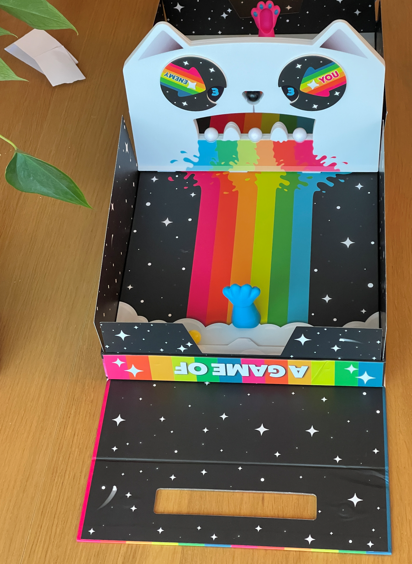
A while back I made a Two Button Game written in Python and using a Raspberry Pi. I wondered how easy it would be to convert it to use a Raspberry Pi Pico device. So at 1:00 pm I started and by 2:00 it was all working on the device. This is not because I’m clever. It’s because of the effort they have put into making the process smooth. These are the things I learned doing the conversion.

  • Creating and deploying Python programs is very quick to do. I used the Thonny program which lets you edit and deploy your code. The latest version even helps you get MicroPython onto your Pico.

  • You can power the device from a wide range of sources. I should be able to halve the number of batteries I have to use in my little game, and they should last a lot longer.

  • You have to search around for some of the code you’ll need, but the application notes are a great start. I got the code to control the NeoPixels from there.

  • There are some really interesting features on the new chip. It has special hardware to automatically generate sequences of pulses without the involvement of your code. It has two processors which can run at full speed together. It has a real time clock. You can use a second Pico device to read the debug signals from a first and provide hardware level debugging. it will act as a USB host, so you can hang a keyboard or a mouse off it.

  • The Pico device has been designed to be easy to mount on a PCB so that it can form the “heart” of a device which needs a few more components.

This is a lovely new device for developers and hobbyists. The fact that you are buying it from a UK suppler makes using it much easier and I really like the idea of a UK company making something as gosh-darned useful as this.

From a performance perspective the Raspberry Pi device stands up very well against the ESP32 that I would normally use. The only snag (and I think it is a big one) is that there is no wireless connectivity. You can connect a Pico device via serial, USB, I2C and SPI but all these use cable. The ESP32 device that I normally use provides both Bluetooth and WiFi connectivity. I really, really, really hope that the Raspberry Pi people have a roadmap for the platform that includes popping WiFi and Bluetooth on a future Pico board. Because then it would be unbeatable.

Update: Ha. Digital dyslexia. I got the number of the chip the wrong way round in title of the original post. It’s fixed now.

MAX7210 Display Warning

20210120_193356319_iOS.jpg

Sometimes I surprise myself with how stupid I am. And sometimes I surprise myself with how clever I am. These events seem to level out, which I suppose makes me a balanced kind of a person.

Anyhoo, today was one of the latter occasions. I’d bought some more MAX7210 displays from Amazon and today I wired them up and put them in little boxes. One worked fine, but the other was very broken. The display was corrupted and didn’t seem to respond to the microcontroller.

I took a proper look at the board and discovered that the input connector had been soldered to the output end of the board. These boards are designed to be chained together to make long displays. Normally the output is not connected.

I dug out a replacement connector and soldered it into place. And then the display still didn’t work. Wah. Then it occurred to me that if the connector was in the wrong place it might be that the whole board had been assembled upside down. This meant that the led arrays would have been fitted the wrong way up. I flipped them over and they worked. Go me!

Of course a super intelligent Rob would have checked the board before he put the devices together. I’m sure that’s what you’d do, dear reader. But I’m still a bit pleased with myself for getting it to work.

BitLocker Recovery Keys are scary

surface go scary.png

If there’s one thing guaranteed to get my pulse racing its a screen like this. It popped up half way through some updates that my lovely Surface Go was doing. Fortunately, once I’d recovered from the shock, I remembered that I’d seen it before ages ago on some machine or other. The solution to this scary problem is not to search for your Recovery Key, it is to hold down the power button until the machine shuts down. Then reboot and, with a bit of luck, the machine will just recover and start up as normal. That’s what my machine did.

If yours doesn’t you will have to find your key. The good news is that recovery keys seem to be assigned to your Windows account, not on a per-machine basis. So you can use another machine to log into your account and get them.

Do I dare?

I got some new button batteries recently. Each of them had one of these stickers on which are supposed to taste horrible, to stop babies from eating them. I really want to lick the sticker to find out what it tastes like, but I’m worried that it might be coated with the same thing that the put on Nintendo Switch game cartridges (also to stop them being eaten). Apparently that is a truly horrible taste that takes ages to go away.

Broken Printer (again)

brokenuna2.png

I think 3D printers exist in one of two states, they are either broken or not broken yet. I thought I’d print some “Obstinate Orange” filament in Una so I swapped out the rather nice pale blue I’ve been using for a while.

Una doesn’t like “Obstinate Orange”. It seems to have blocked her print head. I think this is because when I re-assembled things last time I left a tiny gap in the path the filament takes to the heater block. This tiny gap now holds a plug which has blocked things up.

It’s annoying because Una has been printing some nice boxes and cases. Oh well, I’ve got some more replacement parts on order, I’ll see if I can put things back together in a better fashion next time.

Walkabout Mini Golf for Oculus Quest

walkabout mini golf.png

We spent a couple of hours last night playing Walkabout Mini Golf on the Oculus Quest. It’s rather good (as if we’d spend any time at all playing a game that is rubbish).

It’s miniature golf, but without the windmills. You get five different themed courses, each of which has a more tricky “night-time” mode. The environments are lovely, the physics works well and the group play is very well realised. It’s also very reasonably priced. Very strongly recommended.

Build a nice place to fail

failure.png

When I start work on a project I try very hard to make myself a nice place to work. For the Connected Little Boxes project I’m also making a nice place to fail. When a device goes wrong I want to have an easy way to find out what happens. The latest version of the software sends an MQTT message each time it wakes up giving the reason it was reset.

This will help me determine why a device fails. It should also make it possible for me to build something that tells me automatically when bad things are happening.

Using the MAX7219 display

Dot Matrix text.png

I thought it might be fun to display text on a MAX7219 display. The display is organised as a block of 64 pixels and a built-in chip takes care of keeping each led lit. The blocks can be chained together so that you can control the entire display from just three data connections. I used this software, which works a treat. The only change I had to make was to set the hardware type to MD_MAX72XX::FC16_HW to match the panels that I’d bought from Amazon. You can get two four block panels (like the one above) for around 12 pounds, which I think is good value. You can display text or graphics and even set the brightness (which is very useful if you want to cut down on power consumption).

The only thing that I fell over concerns how the update works. I’m used to making changes to the display and then calling an update function to have the changes applied all at once. This is usually the best way to get smooth graphics. I did this with the driver software and got lots of flicker when scrolling. It turns out that the display is updated after every draw operation unless you call a version of the update function with a command to tell it not to do this:

panel.update(false);  // stop automatic update

// do your drawing here

panel.update();     // display the changes

The code above shows how it works. The first call of update says “stop updating while I draw”. The second call applies all the draw operations at once. This makes things a lot smoother.

Using the ADC on a Wemos ESP8266 device

I want to use an analogue to digital converter in my Connected Little Boxes project to convert a rotary position as set by the knob on the left hand box in the picture into a number I can use to control the servo on the right hand box. I like the idea of moving physical movement from one place to another.

An analogue to digital converter (ADC) is a piece of hardware that takes in a voltage and gives you a number that represents the level of the voltage. ADCs are useful to measure things like the battery voltage levels and for converting analogue sound signals into a sequence of digital values.

A potentiometer is a special kind of resistor. Turning the shaft of the potentiometer moves a contact along a circular carbon film in a way that allows the output to produce a different voltage output depending on the position of the contact. If I connect the output of the potentiometer into the ADC of my ESP8266 I can write a program that will read the position of the potentiometer and use this to control the servo.

wemosADC.png

The ESP8266 chip has a single ADC device which reads signal levels up to 1.8 volts or so. The good news is that my favourite ESP8266 based device, the Wemos D1 mini, has a “potential divider” circuit on the board that allows the input to accept inputs up to the 3.3 volt power supply. You can wire it up as shown above. Remember to use the 3v3 pin rather than the 5v one. Turning the knob on the potentiometer will move the input on the A0 pin between 0 and 3.3 volts.

You can use the ADC in your program like this:

int reading = analogRead(0);

If the input sees 0 volts you get the value 0 set in the variable reading. If the input sees 3.3 volts you get the value 1023. The numbers are fairly steady, although I see a bit of noise which causes the values to “jitter” around a bit. I’ve added some code that ignores changes of around 5 or so in the value.

I send the reading value across to the little box on the right of the picture above so that the position of the servo tracks the knob. It works really well, but in making it work I learned something which you might find useful to impress people with at any parties (or Microsoft Teams meetings) that you might go to in the future.

ADC Problems with the ESP8266

It turns out that reading from the ADC on an ESP8266 gets in the way of setting up a WiFi connection. If the device is connecting to a WiFi access point and your program reads the ADC while this is happening the connection will not be setup properly. I’ve had to modify the code so that it only starts to read from the ADC once a connection has been established.

ESP Reset Message Strings

Have you ever wanted to print out the reason why your ESP32 or ESP8266 has just reset?

No?

Must be just me then. Anyhoo. If you do want to do this, here’s the code to do it. You’re welcome.

void getBootReasonMessage(char *buffer, int bufferlength)
{
#if defined(ARDUINO_ARCH_ESP32)

    esp_reset_reason_t reset_reason = esp_reset_reason();

    switch (reset_reason)
    {
    case ESP_RST_UNKNOWN:
        snprintf(buffer, bufferlength, "Reset reason can not be determined");
        break;
    case ESP_RST_POWERON:
        snprintf(buffer, bufferlength, "Reset due to power-on event");
        break;
    case ESP_RST_EXT:
        snprintf(buffer, bufferlength, "Reset by external pin (not applicable for ESP32)");
        break;
    case ESP_RST_SW:
        snprintf(buffer, bufferlength, "Software reset via esp_restart");
        break;
    case ESP_RST_PANIC:
        snprintf(buffer, bufferlength, "Software reset due to exception/panic");
        break;
    case ESP_RST_INT_WDT:
        snprintf(buffer, bufferlength, "Reset (software or hardware) due to interrupt watchdog");
        break;
    case ESP_RST_TASK_WDT:
        snprintf(buffer, bufferlength, "Reset due to task watchdog");
        break;
    case ESP_RST_WDT:
        snprintf(buffer, bufferlength, "Reset due to other watchdogs");
        break;
    case ESP_RST_DEEPSLEEP:
        snprintf(buffer, bufferlength, "Reset after exiting deep sleep mode");
        break;
    case ESP_RST_BROWNOUT:
        snprintf(buffer, bufferlength, "Brownout reset (software or hardware)");
        break;
    case ESP_RST_SDIO:
        snprintf(buffer, bufferlength, "Reset over SDIO");
        break;
    }

    if (reset_reason == ESP_RST_DEEPSLEEP)
    {
        esp_sleep_wakeup_cause_t wakeup_reason = esp_sleep_get_wakeup_cause();

        switch (wakeup_reason)
        {
        case ESP_SLEEP_WAKEUP_UNDEFINED:
            snprintf(buffer, bufferlength, "In case of deep sleep: reset was not caused by exit from deep sleep");
            break;
        case ESP_SLEEP_WAKEUP_ALL:
            snprintf(buffer, bufferlength, "Not a wakeup cause: used to disable all wakeup sources with esp_sleep_disable_wakeup_source");
            break;
        case ESP_SLEEP_WAKEUP_EXT0:
            snprintf(buffer, bufferlength, "Wakeup caused by external signal using RTC_IO");
            break;
        case ESP_SLEEP_WAKEUP_EXT1:
            snprintf(buffer, bufferlength, "Wakeup caused by external signal using RTC_CNTL");
            break;
        case ESP_SLEEP_WAKEUP_TIMER:
            snprintf(buffer, bufferlength, "Wakeup caused by timer");
            break;
        case ESP_SLEEP_WAKEUP_TOUCHPAD:
            snprintf(buffer, bufferlength, "Wakeup caused by touchpad");
            break;
        case ESP_SLEEP_WAKEUP_ULP:
            snprintf(buffer, bufferlength, "Wakeup caused by ULP program");
            break;
        case ESP_SLEEP_WAKEUP_GPIO:
            snprintf(buffer, bufferlength, "Wakeup caused by GPIO (light sleep only)");
            break;
        case ESP_SLEEP_WAKEUP_UART:
            snprintf(buffer, bufferlength, "Wakeup caused by UART (light sleep only)");
            break;
        }
    }
    else
    {
        snprintf(buffer, bufferlength, "Unknown reset reason %d", reset_reason);
        break;
    }
#endif

#if defined(ARDUINO_ARCH_ESP8266)

    rst_info *resetInfo;

    resetInfo = ESP.getResetInfoPtr();

    switch (resetInfo->reason)
    {

    case REASON_DEFAULT_RST:
        snprintf(buffer, bufferlength, "Normal startup by power on");
        break;

    case REASON_WDT_RST:
        snprintf(buffer, bufferlength, "Hardware watch dog reset");
        break;

    case REASON_EXCEPTION_RST:
        snprintf(buffer, bufferlength, "Exception reset, GPIO status won't change");
        break;

    case REASON_SOFT_WDT_RST:
        snprintf(buffer, bufferlength, "Software watch dog reset, GPIO status won't change");
        break;

    case REASON_SOFT_RESTART:
        snprintf(buffer, bufferlength, "Software restart ,system_restart , GPIO status won't change");
        break;

    case REASON_DEEP_SLEEP_AWAKE:
        snprintf(buffer, bufferlength, "Wake up from deep-sleep");
        break;

    case REASON_EXT_SYS_RST:
        snprintf(buffer, bufferlength, "External system reset");
        break;

    default:
        snprintf(buffer, bufferlength, "Unknown reset cause %d", resetInfo->reason);
        break;
    };

#endif
}

You pass the function a pointer to a buffer and the size of that buffer. The function then works out what kind of device you are using and then creates a message for that device. This is how you use it:

#define BOOT_REASON_MESSAGE_SIZE 150
char bootReasonMessage [BOOT_REASON_MESSAGE_SIZE];
getBootReasonMessage(bootReasonMessage, BOOT_REASON_MESSAGE_SIZE);
Serial.println(bootReasonMessage);

Printing Lithopanes

The 3D printed image

The 3D printed image

What it looks like

What it looks like

A lithopane is a 3D printed surface in which the thickness of the object reflects the brightness of the image that that point. I’ve done a bit of this kind of thing myself in the past with the Kinect sensor and so I thought I’d try some with the new printer. I used a web based service you can find here which takes an image and provides you with an STL file you can then slice and print. I had a go and I’m very impressed with the result. It’s quite something when a lumpy bit of plastic suddenly turns into a proper picture.

If you want to have a go (and if you have a 3D printer you should) make sure you check the options to select a Positive image. I forgot this vital step and ended up with a negative image after four hours of printing.

The Game of Cat & Mouth is really silly fun

cat and mouth.png

After playing lots of deeply complicated games it’s nice to find one that is just silly, frantic, fun. The Game of Cat & Mouth is just crackers.

You use a plastic cats paw with a magnetic spring in the base to fire little balls through the cat’s mouth in the middle. If you knock all the balls in the teeth into your opponents side you win. If you manage to knock out the black nose you win instantly. The game itself is a triumph of design in cardboard, it packs neatly up into a little case .

When you play it you won’t care that much about whether you are winning or losing because you will be laughing too much. Until you lose. Then you’ll want to play again to get your revenge.

It’s deeply silly, and can get surprisingly skilful and strategic. It’s only for two players, but there are variations for larger parties.

Getting the Cube MOT'd

cube.png

I’ve just organised the MOT for our Nissan Cube. This is an important part of car ownership in the UK. The test makes sure that your car is still mostly metal and has working brakes and things, which posed significant problems for a Mini I owned a very long time ago.

Unlike the very first lockdown, this time the garages are all open and MOTs will expire at the set date. The garage where I booked the test had lots of free slots, so I’m wondering how many people know this.

Using ESP32 and ESP8266 with the same source file

If you want to use the same solution on both ESP8266 and ESP32 devices you find that there are a few inconsitencies between their libraries and include files. I've made this tiny set of conditional includes which pulls in the properly named elements for each processor. It also provides a symbol called PROC_ID that returns the processsor ID in a way that can be used in both types of program.

#if defined(ARDUINO_ARCH_ESP32)

#include <Arduino.h>
#include <WiFi.h>
#include <DNSServer.h>
#include <WiFiUdp.h>
#include <WiFiServer.h>
#include <WiFiClient.h>
#include <WiFiClientSecure.h>
#include <HTTPUpdate.h>
#include <WebServer.h>

#define LED_BUILTIN 2

#define PROC_ID (unsigned long)ESP.getEfuseMac()
#define PROC_NAME "ESP32"

#endif

#if defined(ARDUINO_ARCH_ESP8266)

#include <Arduino.h>

#include <ESP8266WiFi.h>
#include <PubSubClient.h>
#include <WiFiClientSecure.h>
#include <ESP8266httpUpdate.h>
#include <ESP8266WebServer.h>

#define PROC_ID (unsigned long)ESP.getChipId()
#define PROC_NAME "ESP8266"

#endif

Just put this at the top of your program and when you build your program it will pull in the files that it needs.

Pandle for free business accounting

pandle.png

If you’ve got a small business or you’re a sole trader you might like to take a look at Pandle. I’ve just signed up for a free account which lets me use their web based services to create suppliers, customers, invoices and all the other accounting paraphernalia that you need to run a company. It has tools that let you produce reports which include the Profit and Loss one (which I think Pandle is named after).

The web based user interface works well and it looks like it will suffice for my modest business needs. If I need the features of the paid service level it only costs a fiver a month. I had a question about the system and it was answered, by a person, within twenty minutes of me asking it. Excellent service.

Well worth a look.

Become a better programmer: Watch this video

This is a great video. I think every programmer should watch it. It was given at “C++ on Sea”, a splendid conference that I’d love to go to one day. But you don’t have to know any C++ to learn from it. The video describes the way that emotions end up in program code. And how to make sure that the emotions that you put in what you write are positive ones.

If I was still teaching I would make sure that all my first year students watched this. And I’d also change the marking schemes for software projects to include some consideration of it specifically. Not because I think you can mandate this kind of behaviour, but because I would want my students to find out first hand the benefits of doing it.